Monday, March 28, 2022

Panel and Avionics

 After many hours of laying out our panel in software, we got a builder friend who's also building a Highlander, to cutout a temporary panel in press-board on his Shopbot CNC.  A few issues were found in the cutout that will be fixed in the next pass.  With some minor tweaking the panel was assembled and placed into the cockpit area to check for interference issues.  None were found.

Panel minus Garmin G5

The transponder we chose for our project is the remote mounted Garmin GTX-45R.  The mounting tray for the transponder needed to be mounted in the fuselage and we chose to mount it behind the baggage area.  A WAAS GPS will also be needed to feed the transponder and a mount was also fashioned and attached to the transponder mounting bracket.

Transponder and GPS mounting bracket

Mounting bracket installed in the aft Fuselage area

Hours: 12


Saturday, March 26, 2022

Cowl work, Drain valve, fuel site tube

We spent several hours making small incremental cuts on the top and bottom cowl, along with judicious sanding, in order to get the top and bottom pieces to fit together properly.  At first we didn't think they could ever fit, but the fit wasn't bad once modified.

Top and bottom cowl fit after trimming

Some brass elbow adapters and tubing were installed on the header tank for a fuel site tube.  Versilon SE200 clear tubing (from McMaster Carr) was used for the site tube as it has an inner liner that is resistant to ethanol.  
Fuel site tube

A drain line was also installed from the header tank to a fuel valve under the fuselage (for fuel testing or draining). Due to the shape of the fabric underneath, we were unable to use some of the parts from our kit, but we purchased a 1" brass bulkhead fitting (1/4 NPT) which worked well.  Also, an inline fuel filter was installed.  A filter here was recommended by several builders as it will catch any debris that could cause the fuel valve to start leaking.  Hours: 14

fuel drain line with filter

Curtis drain valve installed on bottom

Monday, March 14, 2022

Firewall trimming, Boot cowl drilled, fuel pump bolts

The boot cowl was fitted in place, then match drilled to the holes in the fuselage.  The lower edge was trimmed a little more.  With the boot cowl in place, we could then proceed with the firewall fitting.

The engine and engine mount were removed so that we could create a posterboard template for the titanium firewall.  After making the template, we laid it over the titanium firewall sheet, and trimmed it (with snips) to match. 

Template in place over firewall material

The firewall edge was deburred, and installed with clecos.  We left about a 1/4 inch gap between the top of the firewall and the boot cowling, and a gasket (provided by Just) will be installed on the firewall later which will fill this gap.

Firewall fits nicely.

Finally, the engine mount and engine were reattached. 

Firewall and engine attached

We also did a little work on the fuel pump installation, torqueing down the mounting nuts on the bottom of the fuel pump housing.  The aft nut was tricky to get to, but we found that by rotating the whole pump mounting bracket, we could get easier access to the rear bolts... and then refasten the bracket in place afterwards.  Hours: 8

Wednesday, March 9, 2022

Panel Layout

 After a lot of work on both the panel and wiring diagrams we think we've got our final layout.  FreeCAD was used to layout the panel in 3D.  This allowed us to check for behind the panel obstructions.  The COM radio (Garmin GTX200B) was the main item we had to worry due to some cross support tubes.  KiCAD was used to draw the wiring diagram (schematic).  This allowed us to know how many switches and circuit breakers to place on the panel.  Hours:20

"Final" Layout

FreeCAD: https://www.freecadweb.org/

KiCAD:  https://www.kicad.org/


Temp Engine Install and Cowl Fitting

We hung the engine on the fuselage which was a nice accomplishment, even though this is only temporary until we can get a template for the firewall made.  Once we have a template, then we will remove the engine and work on the firewall installation.

Installing the engine

In order to make a firewall template, we first need to fit the boot cowl, which is turning out to be a bit of an effort as we want to make sure everything lines up and that the positioning works with our aftermarket Dentz windscreen.

The cowling pieces are oversized so need to be carefully trimmed, then positioned carefully to get all the panels to line up.  We are making changes slowly as it's much easier to trim fiberglass than it is to put more back on.
Fitting the boot cowl

We also set the windscreen in place temporarily to see how it lines up with the boot cowl.  We'll have to do some more trimming along some edges of the boot cowl, but overall it looks decent. 

Fitting the boot cowl

Once we had the boot cowl where we wanted it, we drilled holes to attach it to the mount points on the fuselage.  After finishing this, we were able to install the cowl with clecos and take some better measurements to check it all out. Unfortunately, we found a few issues.  One was that our firewall is a little too short (about 1/2 inch) to reach the top of the cowling.  This is more gap than we want, so we are going to drop the cowling a bit.  The other issue was that part of the cowling was bowing out a little bit at the front corners.  Not a bad issue, but we want to improve it.  We epoxied over the holes we already drilled, and also added four small fiberglass spacers to the inside of the cowling to alleviate some of the bowing that occurs when fasteners are installed.

Lastly, we wanted to see how the exhaust fits, so we (temporarily) hung the exhaust and muffler.  Looked great!  This will also allow us to check how much clearance we have with the lower cowl.  Hours: 12

Hanging the exhaust system

Friday, March 4, 2022

Ring Mount and Waterpump

We bolted the Rotax ring mount to the engine, which was a bit more challenging than we initially thought it would be.  We had to remove the waterpump and a few hoses first.  And lining up a few of the the bolt holes, which are hard to access, while inserting tight washers was some fun, too.  But we managed to get the ring mount installed and torqued down to the engine.
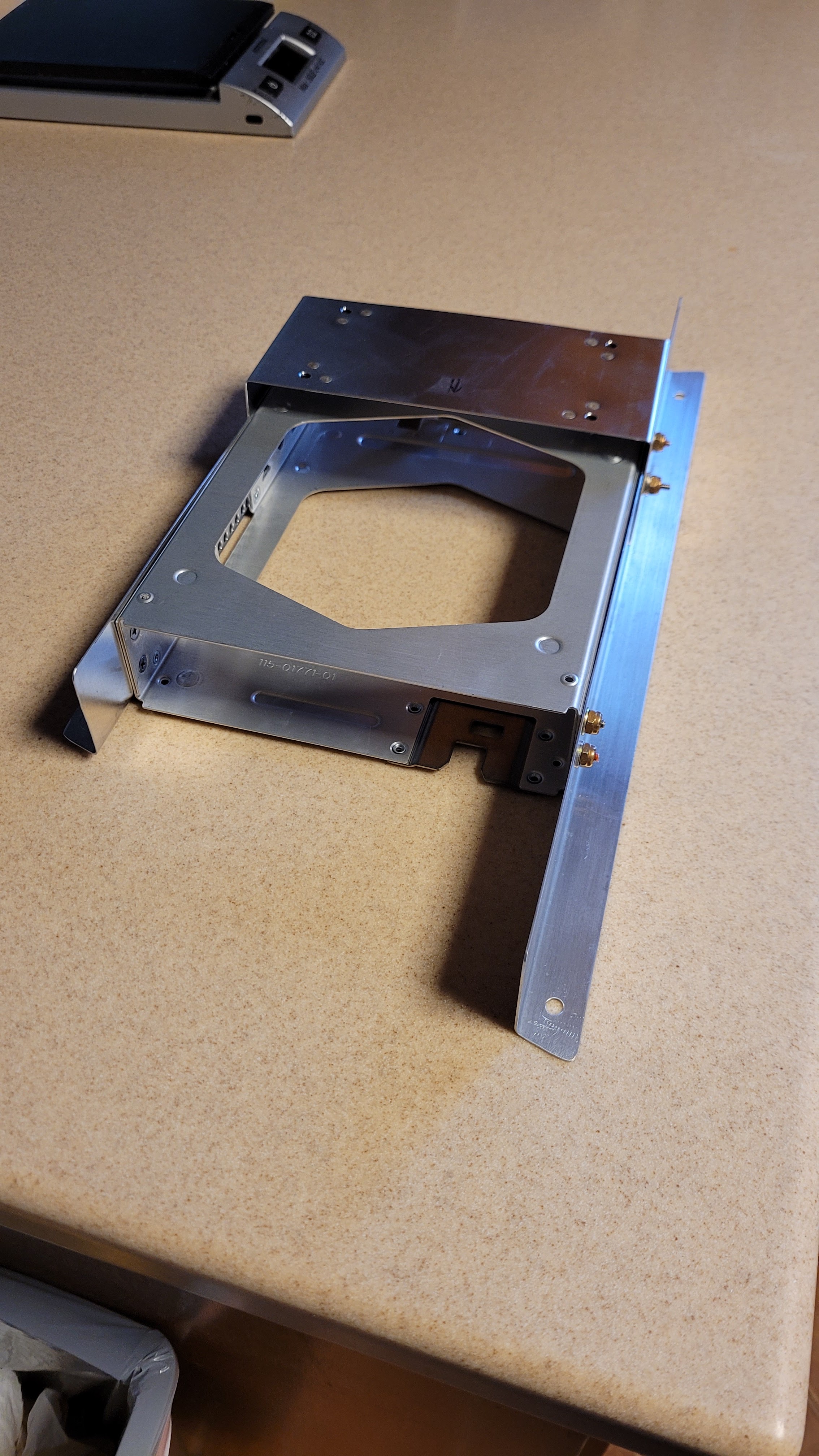
Ring mount (white) installed

However, we had another surprise when we went to put the waterpump back on.  The inlet/outlet ports on the left side of the waterpump now interfered with the freshly installed ring mount.  So we called our Rotax Rep (Lockwood Aviation), and they confirmed that the engine as shipped from the factory did not have the correct outlet port configuration for use with the ring mount.  We needed a 20 degree elbow on the top left port, and the lower left port elbow needed to be rotated.  We ordered new elbows and a new waterpump gasket and waited for parts again.

Removing the two elbows on the left side of the waterpump was not trivial.  They have to be heated to at least 80 degrees C, and then rotated carefuly so as not to damage anything.  The waterpump is aluminum and works like a good heatsink.  We couldn't get the temperature quite hot enough with 1 heat gun, but we had a 2nd one on hand, and with 2 heat guns we were able to get it hot enough (The heat softens the locktite that is used to seal and hold the elbows in place).  Once the elbows were off, we cleaned the threads.

When the new parts arrived in the mail, we screwed on the new elbows temporarily until we could get them lined up properly.  We put the waterpump back on and rotated the elbows until we had them in the correct position, then we marked the position with a sharpie.  We removed the waterpump and elbows, applied a good coating of green locktite on the elbow threads (as recommended by Lockwood), and then screwed them back into place until they were lined up with the sharpie marks.  Then we let it sit for over 24 hours so it could cure.
Waterpump housing with 2 new elbows installed

We installed the waterpump with a new gasket, and then installed the coolant hoses.  It all looks good now, so we can move forward with the engine installation. Hours: 15
Ed installing the waterpump

Michael installing coolant hoses