Showing posts with label Engine. Show all posts

Wednesday, August 2, 2023

Taxi test; coolant temp check, fuel system

Another taxi test was performed, this time watching the coolant temps closely since they were a bit high last time when running with the top cowl off.   This time, we kept the top cowl on to keep airflow as it would be during normal taxi, and the results were very good.  Coolant temps remained within the green. Outside temps were about 10 degrees cooler (87) than the last test, but coolant temps varied between 204 and 217 during taxi test which was over 35 degrees cooler than the last test. 

Michael checking coolant temps during taxi

Also, we double checked the fittings that were tightened last time (at bottom of left fuel tank, and at bottom of header tank).  No fuel seepage was detected so looks like these are now fixed.  

Lastly, we attached a small zippered plastic pouch to the left footwell panel which will hold our airplane registration and other documents that need to remain in the airplane.  Hours: 3

Monday, July 31, 2023

Engine idle adjustment, Fuel system

We adjusted the idle on our engine, as it was idling too low (below 1400 RPM).  By turning the idle screw a bit at a time and retesting, we found that a total of 5 whole turns clockwise was needed to get it to 1700 RPM where it was idling smoothly. 

We started to do another taxi test, but cut it short because our coolant temperatures were getting too high.  We had the top cowl off during this test, so suspect the change in airflow may have contributed to this, along with the very hot outside temperatures (97 degrees).  We will retest this with the top cowl on in near future to check this out. 

We installed a new bingo fuel sensor that arrived in the mail (since the initial one died on us).  The new sensor works great and our low fuel warning light is working again.

We have been smelling some fuel odors in the cabin, but an initial search for leaks didn't turn up anything which was a bit confounding.  However, the odor didn't go away over time, so we decided it was time to go on a more thorough hunt for the source.  By examining every fitting very carefully and closely, we actually found 2 issues.  One was an NPT fitting at the bottom of the header tank.  We could feel one area was slightly moist where a little fuel has slowly seeped out.  This was tightened to seal the leak.  The other issue was at the bottom of the left wing tank, where the fuel strainer screws in.  We had to unfold the wings to find this one.  The fitting was actually bottomed out in the hole, so it could not be screwed on any tighter.  We found a 2nd fuel strainer that had threads cut a little different to fit a bit tighter.  We installed this fitting and reconnected the hoses to the wing.    Hours: 6

Slow leak at bottom of header tank

Slow leak at bottom of left wing tank


Wednesday, July 26, 2023

Fuel tests, flaps, misc prep

 We've been taking care of various miscellaneous things to get ready for inspection.  We performed several fuel tests to determine the unsuable fuel as well as total fuel for our airplane.  Each of the fiberglass wing tanks hold 12.5 gallons, the header tank holds 2.3 gallons.  The unusable fuel in the header is just 8 oz, and the unusable fuel in each of the wing tanks is about 1/2 gallon.   

During the tests, we found that our low fuel detection system was not working.  After some debug, we determined that the sensor itself was bad, so ordered a new one and replaced it. The new sensor is working and our bingo fuel detection is once again up and running.

Bad fuel sensor that was replaced

Fuel flow tests were performed with the airplane in level attitude (which is the critical attitude for this plane), and also tail low (corresponds to nose 15 degrees high).   Tests with individual fuel pumps running, and both running were performed.  Even with minimum fuel, fuel flow through the system was always above 24 GPH  which was very good since our minimum requirement is 9.25 GPH (125% of max fuel consumption).

Fuel was added a bit at a time so we could determine markings of fuel level.  Fuel levels are visible through the fiberglass tanks, so adding markings will give us an approximate fuel level.  A label with markings will be made that will be glued to the tank.

Detailed Fuel flow data is shown below:

We found that our flaps were rubbing a little bit on the flap gap seal in some areas, so carefully bent the edge of the flap gap seals to prevent this from happening.
Wear mark on flap shows where flap gap seal was rubbing

We also adjusted the routing of a wires in the engine bay to avoid potential rubbing, and wire-tied the heater hose valve in place.  Hours: 15

Wednesday, July 19, 2023

Rear baggage wall, W&B, Taxi test

Fabrication of the panels for the rear baggage wall was completed and they were then installed with self-tapping screws.  A power connector located in the center allows for easy connection to a battery charger/tender for our aft mounted battery.  Holes were precisely located for the rudder cables and elevator push/pull tube.  A large notch was cut out on one side (and then covered with plastic) to allow for a good RF (blue-tooth) connection to the transponder which sits directly behind the panel.

Rear baggage wall

A protective cover for the elevator push-pull tube (with lightening holes) was screwed down to the baggage floor.

Elevator push-pull tube cover

We changed out a fuel hose running from the header tank to the Curtis fuel-test valve.  We noticed that the old hose (Versilon SE200 tube) had two small kinks where there were slight bends, so we decided to just replace it with a more robust hose.  The hose we used was a Parker 397 Superflex hose purchased from Aircraft Spruce.

We ran some fuel tests to determine unused fuel levels in the tanks when level.  The two wing tanks which hold 13 gallons each, have about 1/2 gallon of unused fuel each.  The header tank which holds 2.3 gallons has just 8 oz of unused fuel.   

With all parts on the plane (including all inspection covers), we performed a weight and balance check.  The empty weight for our airplane is 824 lbs, and the center-of-gravity came out to be 10.9" aft of the datum (which is the leading edge of the wing).  This works out nicely and is well within the limits of 9-15.5".  We will perform later calculations for most-aft loading and most forward loading, but everything is looking good at this point regarding our weight and balance.

We rolled the plane out of the hangar and did a magetometer intereference calibration.  

Plane pulled out of hangar for a few tests

Then we decided it was finally time to fire it up and taxi it around for the first time.  The airplane fired right up, and we took turns taxiing it around the back of the hangars for several minutes.  This went well and gave both of us a chance to get a feeling for how the steering works with the differential toe brakes.  The steering worked great and we had no problems with taxiing.  Hours: 15

Initial taxi test at KTTA

Tuesday, July 4, 2023

Fuel lines, Painting, Window, Door

Finished up some priming and painting (vestal white) on several parts, including the aluminum turtledeck, two butt-rib fairings, two wing cuff fairings, and the comm. antenna base.  This completes all the painting, minus a few inspection plates that will be done later.


The right side Lexan window was installed (riveted in place).  The left side wasn't installed yet because we were still using the opening for easy access to the fuel lines on that side.


Clear plexiglass window riveted in place

Fuel lines were run from the left wing to the header tank which included a cutoff valve.  This valve will normally be left open, but can be closed when the plane is parked on a slope to prevent fuel from cross-flowing from one wing into the other.  We determined that it is nearly impossible to reach this valve when seated and buckled in as it is directly behind the pilot.  So as a safety feature, we added a control cable for push/pull control of the valve.  This allows the valve to be opened if it is inadvertently left closed prior to takeoff.

Red pull knob installed next to the main fuel cutoff switch

Ed tightening a stop nut for the cross-flow cutoff valve

The pilot side door was installed.  We found a tiny crack in the Lexan near one of the rivets after installing the door.  A tiny hole was drilled in the Lexan at the end of the crack to prevent it from spreading.  Hours: 30

Michael drilling small hole in Lexan

Wednesday, June 28, 2023

Pitot-Static and AOA lines, Fuel lines, Turtedeck Clips, Priming

After taking a week off from the project for vacation time, we got back to work on the airplane.

We fixed the blue tubing that was inadvertently damaged when opening/closing the wing.  This tubing was for our angle-of-attack (AOA) sensor.  The bad section was cut out, and the tubing ends were then spliced together with a coupler fitting.  Once repaired, the Pitot tubing (green) and AOA tubing (blue) were run from the wing to the Garmin GSU25 (which is attached to the back of the G3). A static line (clear tubing) was also run from the GSU25 to a spot behind the panel.  The Pitot and static tubes have Teed connections that run to our backup instrument, the Garmin G5.

Pitot, AOA, and Static lines installed

We riveted on a couple of small clips to the turtledeck.  This should help keep the turtledeck secured in the center since the spacing between quarter turn fasteners was a bit long.

Clips added to the turtledeck.

On the passenger side, a few new fuel hoses were made.  The upper one is for a vent line to the tank, and the lower line is the fuel outlet port. The vent line was tricky as it had to be routed under the root rib to avoid being pinched when opening and closing the wing.  We found that a 150 degree hose end allowed the hose to be routed nicely back on itself.  Protective Tessa tape was applied around the hose to give it some extra protection where it runs under the root web.  A secondary protective sleeve was also applied around part of the fuel and vent lines to prevent any chafing when opening and closing the wing.

Vent (left) and fuel line (right) connected

A few parts were primed, including two fairings (used where the wing and windscreen meet), and the Com antenna base.  A few pinholes were found in the fairings, which is pretty typical for fiberglass parts.  These were fixed, sanded, and another coat of primer applied.  Hours: 14

3 primed parts

Thursday, June 15, 2023

Glare shield, Fuel lines, W&B check

Another fuel hose connection was completed, and we now have a shut-off valve between the left wing and header tank.  This shut-off valve can be closed to prevent fuel from cross-feeding between the wings if parked on a slope.                                     

Fuel hose from right tank to shut-off valve

A flat black vinyl covering was applied to the glare shield, and two small GPS antennas (backups for the G3x and G5) were installed on top.   A test fit of the glare shield was done and we're happy with how it looks.  Final installation of the glare-shield will wait until we finish some other work behind the panel (pitot-static routing and wiring cleanup).  We also removed a protective film covering from the windshield so we can finally see out the front windshield!

Flat black glare shield in place

Next we did a quick check of the weight and balance to see where we stand now.  The plane is a bit heavier than average, which was expected to some degree because of our choice of engine and nose-gear, plus the added auto-pilot.  Right now, the empty plane weighs 808.6 lbs and it will gain a few more pounds before completion. The empty CG is currently about 10.8 inches aft of the datum, which falls nicely in the target range (9" to 15.5" inches).  A quick check with added passengers and fuel indicates that we are in decent shape, but we'll do more exact calculations once everything is complete.  Hours: 4.5

Wednesday, June 14, 2023

Flap gap seals, Fuel lines

Now that the flaps are finally installed, we decided to install the flap gap seals, which are aluminum strips that span the gap between the wing and the flaps.  We had previously primed and painted these pieces, so all we had to do was rivet them to the wings.

Flap gap seals installed

More time was spent planning out the fuel lines from the wings to the header tank. The wings were folded several times during this process as we need to ensure that the hose routing and hose lengths will accommodate folding of the wings.  Hose ends were attached to complete two of the hoses that run to the header tank.  We are waiting on parts to finish the remaining hoses.

Right angle connectors installed on upper hoses

Additionally, work has started on installation of the rear baggage panels.  We found that a few attachment holes that were drilled into these panels no longer line up with the holes in the chassis tabs.  This may have been due to flexing of the tubes that occurred when shrinking the fuselage fabric.  We may just remake that panel as we have some spare aluminum sheet.

Work is also underway on installation of the glare-shield.  Some right angle brackets were made to help support the glare-shield along the front edge.   Hours: 9

Friday, May 19, 2023

N-Numbers, Aileron cables Regulator heatsink

We finally put our N-number (N371EM) on the airplane.  These were vinyl letters that are the same color as the green stripe.  We also added the Just Aircraft logo to the tail, which was a decal supplied by the factory

Michael adding N-Number and Just logo on right side

Ed adding N-number to left side

Tail with N-number and "Just" logo

After waiting a few months, we finally received a new (optional) heatsink kit for our Rotax voltage regulators which we installed.  Several builders have issues with high temperatures from these regulators which can cause damage to the regulator connectors, and this retrofit (approved and sold by Rotax) helps with this issue.  We expect that this will solve any issues, but we also have the option of ducting cool air to the regulators if early testing indicates they are getting too warm.

New heatsink attached to voltage regulator

We assembled the aileron cables, using nicopress sleeves and thimbles at the attachment points.  A turnbuckle was installed on both the right and left cables behind the seats.  This is where the cables running from the wings attach to the cables running to the controls.

Turnbuckle connection for the ailerons

We also installed a turnbuckle for the aileron pass-thru cable that attaches the two down-aileron cables from each wing.  Hours: 15

Aileron pass-thru cable with turnbuckle

Saturday, March 4, 2023

Leak fixes, Cowl, Door frames, Control sticks

 After last engine runup, we had found we had 2 leaks, one from the brakes and one from fuel.  The brake leak was at the bottom of the Grove landing gear at a right angle fitting. The brakes were drained, and the wheel was removed to get access to the fitting.  The right angle fitting was then removed and cleaned.  Locktite thread sealer was applied, and the fitting was installed with an extra turn to ensure it fit snugly. 

Brake fitting tightened

The fuel leak was coming from a fitting that went from a T-fitting near the fuel filter to our fuel-pressure-sender.  This one was a bit complex because of all the interconnected fittings and hoses.  But this gave us a good opportunity to change our fuel-bypass orifice as we learned ours was slightly oversized ( The ideal orifice size was 0.35 mm, and ours was about 0.88 mm).  Our orifice fitting came from JEGS, and is essentially a hole drilled in a set screw, which is then screwed into a special AN fitting.  Using a small mill with a tiny drill bit, a 0.35mm hole was drilled in the center of a new stainless set screw.  This took several attempts as the tiny drill bits were easy to break, but we got it done.  The new orifice was installed, and the leaks were addressed.  After the fixes, we ran the fuel pumps (which boosts the system to 50 PSI) and checked for leaks again.  None were detected. 

Fuel leak fixed at this T-fitting

The new 0.35mm fuel-bypass orifice is in the top of this T-fitting

The cowl pieces, which had been previously primed, were sanded down with 320 grit sandpaper so that they will be ready for painting, although we won't get to that until the paint booth is back in working order.

Next we turned our attention to the doors.  We previously made a couple of center aluminum strips that cover the seam where twoLexan panels meet.  We wanted to close up the ends of these, so we filled them in with a little bit of epoxy (JB-Weld) which was sanded flat once dry.  This is mainly cosmetic, but does make it look a little nicer when installed. These strips were also sanded lightly to get them ready for priming.

Epoxy added at the ends of center door frame strips

We also wanted to decide on the color to paint the door frames.  We were originally thinking of using gray as that matched most of the interior and existing powder coat, but also considered black as that helps create more of an unobstructed view out of the airplane.  We wrapped the frame in some spare black vinyl we had to get an idea of how it would look.  We liked the result, so we will likely paint the door frames black now. 

Experimenting with black door frames

Lastly, we drilled a couple of small holes in our control sticks for the wires that will go to the push-to-talk switches.  We are going to making the control sticks removable, so plan to add a small connector that will make the wires easy to disconnect.   Hours: 27

Hole drilled in control stick

Thursday, February 23, 2023

Engine test #2, more Cowl work, and misc

We had a run of nice weather, so decided to prep the plane for another ground run.  We bolted the propeller back on, carefully setting the pitch of each blade to keep them within 0.3 degrees of each other.  We decided to keep the cowling on for this test since we had just finished installing the Skybolt fasteners in them.

This time we ran the engine for a longer test period (about 15 minutes), and also ran up briefly at full power to verify the prop pitch.  At full power, our engine RPM needed to fall between 5100 and 5800 RPM to ensure the blade pitch is within limits and safe to fly (per guidance from our prop manufacturer, E-Props).  Ours came up to 5200, so it is good.  We may need to change the prop pitch a bit later once we get to the flight testing stage.  E-Props recommends pitching for 5500 RPM when in flight at full power.

Michael behind the controls for the 2nd engine test run

The test run went well, although we did uncover a few issues after looking everything over after the test run.  We found some drips down by the right brakes, and found two brake fittings that had drips and need to be addressed.  We also found a bit of fuel leaking around the fuel pressure sensor that we will fix.  This shows how important these early tests are as they help flush out these type of issues.  Some brake line compression fittings and a few new fuel hose fittings were ordered and will be installed once they arrive. 

We also did some additional work on the cowling to improve the surface finish.  This included adding a little more filler and sanding. The front ledge of the boot cowling was also trimmed back a bit (about an inch). We decided to shoot a light coat of primer on the three cowling pieces, as this can help to find remaining defects in fiberglass.  We did this outside since our paint booth is currently full of tools and parts.  Not sure why this works so well, but just this little coat of primer really did help highlight some of the remaining irregularities in the surface that we will now fix.  

Light coat of primer on the three cowling pieces

We also wanted to address the cockpit down tubes that are directly in front of the pilot and passenger.  We decided to wrap them with a matte black vinyl to hopefully help mitigate reflections on the windscreen. A 2" wide strip of vinyl perfectly went around the circumference of the two tubes. Hours: 21

Black matte vinyl added to down tubes
 

Tuesday, February 7, 2023

Seats, cowling, fuel site tube

 We replaced the lower cushion foam on the seats with memory foam to make them more comfortable (the factory seats are a common complaint among builders).  3 layers of foam were cut to shape, glued together, and then stuffed into the existing fabric seat covers.  This foam does weigh more than the original foam, but figured that the extra comfort was worth the weight penalty.

New (colorful) seat cushion foam

Some epoxy with flock was added around the fuel door to close up a gap near the hinge and make it look a bit nicer.
Work done around the fuel door

Quite a bit of sanding and filling work (using 3M lightweight filler) was done on all three cowl pieces to shape and smooth them out.  Some lightweight filler was also added around the NACA duct to smooth the transition areas.

Filler work around the NACA duct

Ed getting ready to add some lightweight filler

A protective guard around the fuel site tube was completed, painted black, and installed.  The site tube has a striped pattern behind it to help visualize the fuel level.  Refraction causes the pattern to change when fuel is in the tube.  We also have an electronic fuel bingo sensor that indicates when fuel is low.  This was tested and verified to be working, but we will do some testing before setting the level at which it triggers.
Fuel site tube with stripe pattern.

We also started some work on the right (passenger) door.  The lexan sheets that form the doors were trimmed to fit better against the fuselage.  We still need to do the same for the pilot side door.  Hours: 21

Michael trimming a door panel

Saturday, January 28, 2023

Cowl Baffling, Oil Door, Baggage Floor, etc

Baffling:  To make sure all the air coming into the radiator opening on the cowl actually enters the radiator, we needed to create a baffle seal between the coolant radiator and the cowl.  The radiator provided by Rotax did not have any means to attach a baffle so an aluminum surround was fashioned out of 0.032 aluminum.  It was secured at the four mounting positions of the radiator.  Silicone baffle material was at attached with rivets and rivet washers.  The cowl was installed and the baffle material was marked so that it could be trimmed to fit.

Radiator surround and attached silicone baffle material

Side seal of baffle to cowl

Bottom Seal of Baffle to cowl

The shape of the oil door was tweaked a bit to match the curve of the cowling.  The hinge pin and spring on the oil door were then installed. 

Fuel filter placement was adjusted slightly to improve clearance from the boot cowling.

Baggage Floor:  Two separate thin (0.02") aluminum sheets that formed the baggage floor needed to be modified due to other changes that occurred during fabric covering and fuel routing. Some of the edges were trimmed to prevent interference with the fabric, a hole for the fuel drain was enlarged.  Also, another hole in the floor (no longer needed due to a change in our fuel routing), was patched.

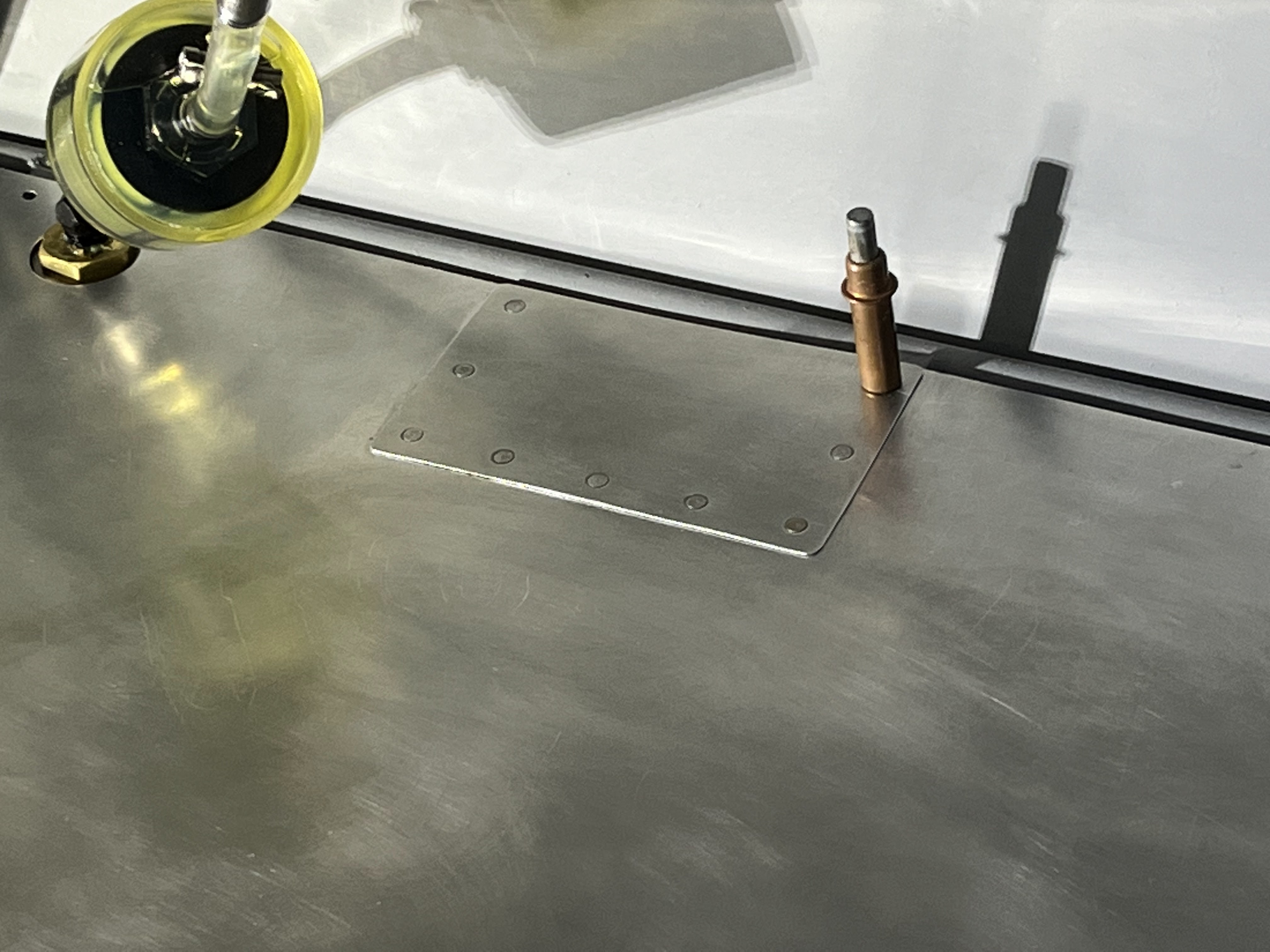
Rear baggage floor with riveted patch and larger hole for drain


Clamps: Four standard Adel clamps (black) were replaced with silicone clamps (blue).  They have a higher temperature rating, but are also the better choice for holding the silicone hoses that they are clamping.  Hours: 15

Blue silicone clamp now holds this silicone hose