 |
| Painted Rudder Pedals |

Thursday, January 14, 2016
Rudder Pedal Paint

Wednesday, January 13, 2016
2nd Axle and Wheel Installation
As we indicated in our previous blog posting, we fixed the brake shoe rubbing the tire. Originally, we had removed three spacers behind the brake disc. This gave us the space we needed so that the brake disc didn't rub the Grove landing gear. But this had the negative result of causing the tire to rub on the brake shoe. After consulting the factory, and a little experimentation, we added two washers in the original spacer location. This gave us sufficient space on the brake shoe and brake disc.
Hours: 1.5
 |
| Original Spacers vs Two 1/4" washers |
 |
| Washer/Spacer location |
 |
| Brake Shoe to Tire Spacing |
 |
| Brake Disc to Grove Gear Spacing |
Tuesday, January 12, 2016
Axle and wheel installation
Had an issue with the left tire rubbing the brake shoe. After discussing with the factory, they suggested adding additional washers behind the brake disk which positions the wheel slightly further away from the brake shoe. Experimented by adding one washer, but there wasn't much clearance, so added 2 washers to each of the 3 bolts attaching the disk to the hub. This provided sufficient clearance and the problem with rubbing was resolved. We plan to duplicate this change on the other (right) wheel, too. Hours: 1.0
Monday, January 11, 2016
Axle Installation
 |
| Axle installed on left side |
Sunday, January 10, 2016
Misc Work
The fork assembly F-3570.4 has bronze bearings
EF202424 inserted into both ends of the pivot tube.

Also sprayed the rudder pedals with self etching primer.
 Hours:1


Saturday, January 9, 2016
Landing Gear Reversal
Found that we had installed the Grove landing gear backwards. The gear was reversed. Had to order AN5-21A bolts for the landing gear as they were not included in the kit hardware. While we wait for the hardware to arrive, we stared assembly of the nose gear parts. Hours: 2
Thursday, January 7, 2016
Wheel assembly
Assembled the two main gear wheels, and the front wheel. To do this, we placed an inner tube inside of each wheel (using some talcum powder to assure it slides inside of the rubber wheel), pushed the valve stem through one half of the wheel, then bolted the other half of the wheel to the first one (6 bolts at 100in-lbs of torque). Main gear tires were inflated to 38 PSI, and front tire was inflated to 29 PSI. Brake rotors were also bolted to the two main gear wheels. Hours: 2.5
 |
| Front wheel and main gear wheels |
Sunday, January 3, 2016
Wheels, Brakes
We decided to start working on the main gear, but after looking at the parts in our kit, there appeared to be a problem with the axles. It looked like the axles needed to be just a little bit longer so that we could bolt them on (using axle spacers from Just) without interfering with the brakes. Because of this confusion, we contacted the factory, and learned that we do not need to use the spacers supplied by the factory. Instead, we can get the existing axles to work by removing the brakes, and then removing small (about 1/2 inch) spacers that are behind the brake discs. By doing this, we have verified that the axles provided will work just fine. Hours: 1.5


Workshop TV
To make our garage workshop a little more "liveable", we decide to install a TV. Bought a wall mount kit, and moved this 32" LCD TV from the spare bedroom to the garage. Works great!
 |
| Workshop Entertainment |
Friday, January 1, 2016
Additional Flooring Work

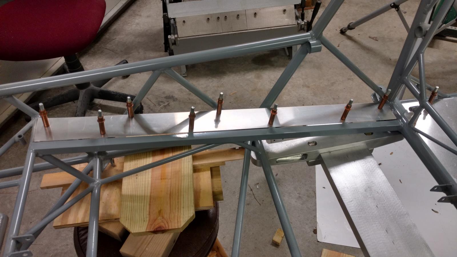
The two flooring panels between the seats and fuselage sides were drilled to final size and all holes and edges were deburred. The flooring panel below the rudder pedals was also drilled to final size and then holes/edges deburred. Hours: 2

Sunday, December 13, 2015
Baggage Flooring
Trimmed and deburred the edges of the aluminum sheets that make up the baggage flooring and back of baggage bay. Additional trimming was done to allow space for the interior finishing fabric to pass between the aluminum sheet and the frame. We also up-drilled the fastener holes for these sheets to the final size (1/8"). These panels are currently cleco'd in place. Hours: 4
 |
| Rear baggage area with flooring |
Sunday, December 6, 2015
Elevator Push-Pull Tube
Installed the short elevator push-pull tube that connects the bell-crank (which also attaches to the long push-pull tube) to the elevator horn. Had to bend the tube up slightly (about 0.5 inch deviation) in front of the front bearing point to alleviate friction. The elevators are not installed yet, so there is currently no connection to the elevator horn. Hours: 1.5
Saturday, December 5, 2015
Control Sticks Installation
 |
| Drilling Control Stick Bolt Hole |
 |
| Control Sticks Installation Completed |
Push-Pull Tube Installation
Installed Long Push-Pull tube, which connects from the control stick mixer to a bell crank in the aft fuselage. The tube had to be bent slightly in front of the front bushing (about 1 to 1.5 inch deviation), and also slightly rear of the back bushing (about 1/2 inch deviation) to relieve binding at the bearing points. Hours: 1.5
 |
| Bending the push-pull tube |
 |
| Push-pull tube attached to horn on control stick mixer |
 |
| Push-Pull tube attached to bell crank in rear |
Friday, December 4, 2015
Bell Crank Installed
 |
| Bell crank installed |
(0.5 hours)
Subscribe to:
Posts (Atom)