 |
| New flap pulley bracket in its happy new home |

Wednesday, February 22, 2017
Left flap pulley bracket attached
Finally, after all the time spent building a new bracket and fixing the alignment, our newly welded and painted left flap pulley bracket was epoxied and riveted in place. Smoothed the excess adhesive after it set-up about 30 minutes, and we avoided having too much excess adhesive this time by lightening up a bit on the amount applied. Hours: 1.0

Monday, February 20, 2017
Flap and Aileron Pulley Work
Once we were happy with the flap pulley bracket it was time to put some primer and paint on it for corrosion protection. We bought some 2 part epoxy primer and Mike sprayed two coats on the bracket. That was followed by two coats of a gloss topcoat paint to match the rest of the airplane parts. Once it is fully dry we will do a final install.
We moved onto the bottom aileron pulley bracket. Again, we were not happy with the alignment of the pulley bracket, so we built another. With the flap pulley under our belts, we were able to make the new bracket much quicker. While Ed did the TIG welding on the new bracket, Mike made four fabric plates that will be used around the two bottom pulleys on each wing. One of the fabric plates is ready to be placed. The other three are in a template form and once a custom notch is done they would be ready for placement as well. Hours: 5
 |
| One completed Fabric Plate, One partially completed Fabric Plate and the bottom Aileron Pulley Bracket drilled and Cleco'd. |
Saturday, February 18, 2017
Left flap pulley fix
Many hours were spent fixing the alignment problem with the left flap pulley. We originally planned on building all new parts, and even carefully bent some steel in order to have the new base match the radius of the spar (see picture below). However, after more thought on the matter, we decided to salvage the base from the original pulley bracket because it had already been drilled (as it was previously riveted) to the spar. So by reusing that piece of the bracket, we didn't have to worry about precisely lining up 4 new holes with the ones already in the spar.
We created two new bracket arms (twice, because we cut the first set just a little too short). Holes were drilled and reamed for the pulley bolt, and the parts were deburred. Using a straight wire that has a 90 degree bend, we determined the correct alignment by lining up the pulley with the holes in the rib and the flap horn.
For the purposes of welding, a couple spacers were made out of steel to maintain the spacing between the arms, and then the pulley was replaced with the spacers. We clamped the arm assembly to the base, and I then welded the bracket arms to the base with TIG, using ER80SD2 welding rod.
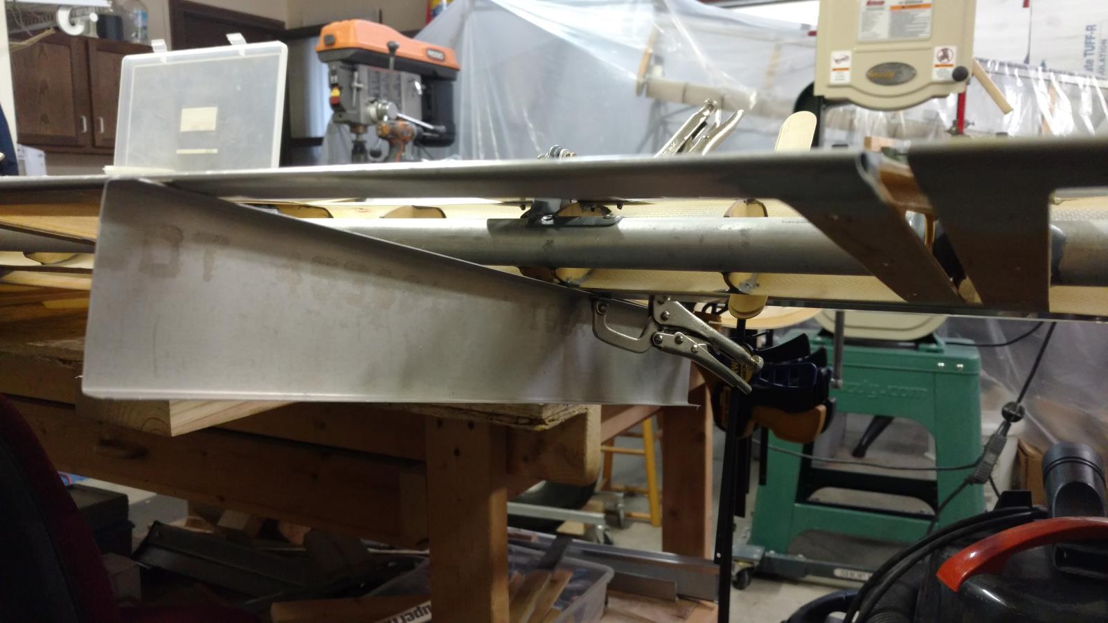
After everything cooled off, we tested alignment by putting it back on the spar (See image below). It's a thing of beauty. The bent rod shows that we now have good alignment from the hole in the rib, to the pulley, and then up to the flap horn. Hours: 10
 |
| Michael is bending some steel around a pipe to set the radius |
We created two new bracket arms (twice, because we cut the first set just a little too short). Holes were drilled and reamed for the pulley bolt, and the parts were deburred. Using a straight wire that has a 90 degree bend, we determined the correct alignment by lining up the pulley with the holes in the rib and the flap horn.
 |
| Ed cutting pulley bracket arms using a cut-off wheel |
After everything cooled off, we tested alignment by putting it back on the spar (See image below). It's a thing of beauty. The bent rod shows that we now have good alignment from the hole in the rib, to the pulley, and then up to the flap horn. Hours: 10
 |
| Bent rod showing good alignment of the newly welded pulley bracket |
Saturday, February 4, 2017
Flap Pulley Issue
Well, we thought we were done with the left flap pulley, but there's a problem. We noticed that once fastened in place, the pulley was slightly angled up and to the left. I think it was probably originally welded like this from the factory, because the back side of the pulley bracket is shaped to fit the spar which fixes it's angle once it is lined up with the flap horn. We hoped this wouldn't be an issue, but to know for sure, we wanted to test the pulleys with cable to ensure there was no problem.
To do a test run with cable, we needed to drill holes in rib webs #1 and #2, which required using the templates supplied in the manual. There-in lies another problem! Turns out the templates printed out from the manual were "squished" a bit (for lack of better word) and did not have the right aspect ratio. Some of the template holes were actually oval instead of round. Don't know about you, but it's pretty hard to drill an oval hole. Some of the templates were worse than others, and when cut out, the original templates were not even the same shape. After some investigation, Michael found that the original images had been resized when inserted into the manual (a Word document). By removing the images from the Word document and copying them into another application, he could recover the originals with the correct aspect ratio. This was a great find and the new templates are all the same shape, and all the drill guide holes were round.
After drilling the cable holes in ribs #1 and #2, we ran a cable through the holes, around the flap pulley, and to the flap horn. We then tested the flap motion by pulling and releasing the cable. It worked, but the cable was rubbing the side of the pulley pretty severely, and you could even feel the extra friction when pulling by hand. Not good, and we both agreed we needed to remove the pulley bracket and fix it. Bad news is that it was already riveted and epoxied in place. After some research, we found that parts like this can be removed by softening the epoxy with a heat gun. We drill out the rivets, and then applied heat with a heat gun (being careful to shield the wood rib and the fuel tank to prevent these from heating up). This worked great, and the flap pulley bracket popped off. Next steps will be to fix the bracket (or maybe even build a new one), in a way that allows the cable to have a smooth motion to the flap horn. This will be more difficult since we now have holes already drilled in the spar, but nobody said building airplanes was easy. Hours: 3
To do a test run with cable, we needed to drill holes in rib webs #1 and #2, which required using the templates supplied in the manual. There-in lies another problem! Turns out the templates printed out from the manual were "squished" a bit (for lack of better word) and did not have the right aspect ratio. Some of the template holes were actually oval instead of round. Don't know about you, but it's pretty hard to drill an oval hole. Some of the templates were worse than others, and when cut out, the original templates were not even the same shape. After some investigation, Michael found that the original images had been resized when inserted into the manual (a Word document). By removing the images from the Word document and copying them into another application, he could recover the originals with the correct aspect ratio. This was a great find and the new templates are all the same shape, and all the drill guide holes were round.
 |
| Drilling out the rivets in the flap pulley bracket |
After drilling the cable holes in ribs #1 and #2, we ran a cable through the holes, around the flap pulley, and to the flap horn. We then tested the flap motion by pulling and releasing the cable. It worked, but the cable was rubbing the side of the pulley pretty severely, and you could even feel the extra friction when pulling by hand. Not good, and we both agreed we needed to remove the pulley bracket and fix it. Bad news is that it was already riveted and epoxied in place. After some research, we found that parts like this can be removed by softening the epoxy with a heat gun. We drill out the rivets, and then applied heat with a heat gun (being careful to shield the wood rib and the fuel tank to prevent these from heating up). This worked great, and the flap pulley bracket popped off. Next steps will be to fix the bracket (or maybe even build a new one), in a way that allows the cable to have a smooth motion to the flap horn. This will be more difficult since we now have holes already drilled in the spar, but nobody said building airplanes was easy. Hours: 3
 |
| Correct alignment shown with a bent solid wire |
Sunday, January 29, 2017
Flap Pulley and False Rib
The spar area around the flap pulley was sanded and cleaned with acetone. The flap pulley bracket was then epoxied and riveted in place with Hysol epoxy and CCP-44 rivets. After a 30 minutes of curing time on the epoxy nice fillets were formed with a wet finger.
We also discovered in the manual that a false rib needed to be installed between Rib #1 and Rib#2 between the rear spar tube and the wing trailing edge aluminum strip. The rib was trimmed for a good fit and then a hole was drilled on both the top and bottom side of the tailing edge aluminum strip thru the false rib cap strip. Everything was disassembled and cleaned. The two holes were dimpled and a countersink was placed in the cap strip holes. Finally the false rib was epoxied and riveted in place using Hysol epoxy and countersunk aluminum rivets. After a 30 minute wait for the epoxy to start curing, a nice fillet was made in the epoxy. Hours: 2.5
 |
| Flap Pulley Bracket Installed |
 |
| False Rib installed. Weight used to keep rib in place until epoxy dries |
Saturday, January 28, 2017
Flap Pulley Block
Planned and prepared for installation of a pulley block in the wing used for control of the flaps. This block was positioned on the rear spar about 1/4 inch from the rib, and lined up roughly with the flap horn. Once we determined the approximate position, we cut a notch in the rib cap to accommodate the pulley. We then carefully measured and re-positioned the pulley block, being careful to line up the pulley with the hole in the flap horn. This was done both by using a long drill bit as a guide, and also sighting by eye, being careful to keep the flap in the 20 degree down position as directed by the manual. Once the position was figured out, we drilled the holes for the pulley block, and attached it temporarily with Clecos. Hours: 1.5
 |
| Michael is touching up a new notch in the rib cap with a file |
Friday, January 27, 2017
Flap/Aileron Pulley Block
We started working on the Flap and Aileron pulley blocks. In order to align the pulleys, the flap and aileron were re-installed and blocks were installed to keep them in the "neutral" position. The mounting holes in the pulley blocks were marked out and center punched. There were 4 mounting holes (one in each corner) in the sole plate of the pulley block, with ¼” minimum edge distance. Hours: 1
 |
| One Flap and two Aileron pulley blocks with holes drilled. Flap pulley block has pulley installed |
Sunday, January 22, 2017
Left Wing Flap/Aileron Hinges
We installed the hinge brackets on the left wing for the flaps and ailerons. Twelve brackets total were installed (6 for the flap, and 6 for aileron). These parts were previously cleco'd in place... so we first removed them, then deburred them, then sanded the mating surfaces, and next cleaned the surfaces with acetone. Then they were installed using Hysol epoxy adhesive and rivets per the manual. Below is an example showing a set of hinge brackets that was installed for the flap. Hours = 2.5
 |
| Flap Hinge Bracket Installed |
Left Wing Aileron/Flap Attach Brackets
Today we started the alignment of the left flap and aileron. In the neutral position, the flaps and aileron should follow the airfoil shape of the wing ribs. As per the manual, this was done by clamping a straight edge material to the wing rib cap strip and extending it outward to set the flap and aileron position.
A 1/8" gap between the wing trailing edge and flap/aileron leading edge is required per the manual. This was accomplished by using 1/8" wooden wedges taped into position.
A lot of time was spent "tweaking" the positions of the flap and aileron to get an equal gap and to make sure the flap and aileron were inline with each other. Once the position of the two parts were set, we aligned the mating attach brackets on each side of the wing rib web. The brackets were tightly clamped and the four rivet holes were drilled through the previously drilled pilot holes, wing rib web and mating bracket. The final hole size was made using a #30 drill bit in a right angle drill due to limited space. Long reach wing-nut clecos were used to temporarily clamp the parts. Hours: 3.5
 |
| Positioning the flap with a straight edge |
 |
| Gap set with wooden wedges |
 |
| Long Reach Wingnut Clecos |
Monday, January 16, 2017
Left Wing Aileron/Flap Attachment
The left wing is really starting to come together. The aileron and flap attach brackets (six for each) were cleaned up and deburred. As per the builder's manual, the brackets were paired up and labeled to keep them together until final assembly. One bracket at each attach point was marked for pilot holes and then drilled and the holes were deburred. A total of six brackets were drilled, three for the flaps and three for the ailerons. The bracket were slid into the slots cut previously with the the drilled brackets on the fuselage side of the wing ribs. The brackets were roughly aligned and then clamped in place. Oil-sintered bronze bushings were placed into the flap and aileron hinges and they were attached to the brackets using AN3 hardware. Some tweaking was done to get the flap and aileron in position. There will be more adjustments done when we resume. Hours: 2
 |
| Flaps(foreground) and Ailerons(background) attached to wings |
Sunday, January 15, 2017
Completed Left Wing Trailing Edge Slots
The remaining three slots were cut in the wing trailing edge. All twelve slots were then deburred. Hours: 1
Saturday, January 14, 2017
Left Wing Trailing Edge Slots
We are in the process of cutting slots in the trailing edge of the left wing. These slots are for the flap and aileron hinges that will (eventually) be attached to the wing ribs and protrude through these slots. The instruction manual suggests chain-drilling to create a slot. We tried this method, and also tried a few other methods including using a Dremel rotary tool with a cutting bit, and a Dremel multi-tool with a vibrating cutting bit. No method seemed superior to another, but regardless of the method used, extreme care was taken so that the ends of the ribs (which are centered between a pair of slots), were not nicked. Once a rough slot was created, the edges were fixed and smoothed with files. One side of each slot was filed back so that it was even with the edge of the rib.
There will be a total of 12 slots in the trailing edge, 6 for the ailerons, and 6 for the flaps. We opened up 10 of them so far, so just have a few more to go for this wing. Hours: 2.5
 |
| Two slots in the left wing for the aileron hinges |
There will be a total of 12 slots in the trailing edge, 6 for the ailerons, and 6 for the flaps. We opened up 10 of them so far, so just have a few more to go for this wing. Hours: 2.5
Tuesday, January 10, 2017
Left Wing Trailing Edge Attachement
We started working on the Left Wing Trailing Edge. First, using a fine saw we cut away the top and bottom rib cap strips in line with the rear face of the rib web. We had to use a straight edge to keep the saw blade square, otherwise it was difficult to keep the saw blade straight. Two pieces of pre-bent aluminum trailing edge material was fit on the wing trailing edge with the two pieces butted up tightly in the middle over a rib spare cap. The two ends were marked and the excess material was cut off. After filing and deburring the material the two pieces were clamped onto the wing trailing edge.
Hole locations were marked and first drilled with #40 bits followed by #30 bits. Once all the holes were drilled everything was disassembled and all the holes were deburred. Since the assembly manual calls for countersunk rivets, the aluminum trailing edge piece was dimpled and the rib cap strip was countersunk. A liberal amount of Hysol epoxy was used where ever the aluminum mated with the rib web and cap strip. The trailing edge aluminum was placed on the wing and aluminum 1/8" countersunk rivets were installed.
After allowing the Hysol epoxy to setup for 30-40 minutes, the excess epoxy was smoothed to form nice transitions and fillets. Hours: 3
 |
| Trailing edge material clamped in place |
 |
| Trailing Edge Attached with Epoxy and Rivets |
After allowing the Hysol epoxy to setup for 30-40 minutes, the excess epoxy was smoothed to form nice transitions and fillets. Hours: 3
 |
| Smoothed Epoxy Transistion |
Monday, January 2, 2017
Left Wing Strut Brackets
Lift Strut Bracket at the leading-edge of the left wing was installed (same process previously described for the lift strut bracket at the trailing-edge). Epoxy adhesive was applied and the part was riveted to the leading-edge spar. After waiting another 30-45 minutes, the epoxy fillets between the bracket and the spar were smoothed.
Jury Strut Brackets were also installed on the left wing. A straight edge was used to span between the two spar tubes, and marks were made 53 inches from the base of the spars at the point where the straight edge contacted the spars. These marks were used to position the jury strut brackets. Two attach holes were drilled (to #40) in each bracket. These brackets were then positioned onto the spars and updrilled to 1/8". The brackets were epoxied and riveted in place, and once again, the epoxy was smoothed after allowing to dry for about 45 minutes. Hours: 4
 |
| Lift Strut Bracket epoxied and riveted in place |
Jury Strut Brackets were also installed on the left wing. A straight edge was used to span between the two spar tubes, and marks were made 53 inches from the base of the spars at the point where the straight edge contacted the spars. These marks were used to position the jury strut brackets. Two attach holes were drilled (to #40) in each bracket. These brackets were then positioned onto the spars and updrilled to 1/8". The brackets were epoxied and riveted in place, and once again, the epoxy was smoothed after allowing to dry for about 45 minutes. Hours: 4
 |
| Jury strut brackets with 2 rivets in each (one is at bottom and other is toward the top of the image) |
Sunday, January 1, 2017
Left Wing Lift Strut Attach Brackets
Even though the Lift Strut Attach Brackets were placed at the factory there is still quite a bit of work to do to get them attached to the wings. First, their placement had to be verified with measurements provided by Just Aircraft. Then the Lift Struts were attached with the provided AN bolts and lifted 3ft to check for no binding in the attach bracket.
Once the location was verified the holes were drill into the spars using the pre-drilled holes in the lift strut attach brackets as guides. Holes were drilled to final size (#30 drill bit) and cleco'd in place.
 |
| Lift Strut installed and checked |
 |
| Ed drilling Holes while Mike look over his shoulder |
After drilling all the holes, everything was disassembled and then deburred. The mating surfaces were abraded and cleaned with acetone. The rear strut attach bracket was then epoxied and riveted in place. There were two sized rivets that had to be used. CCP44 were used when ever the bracket was attached to just the spar, but SSD48 (i.e. longer rivets) were used when the bracket was attached to the spar the then internal I-beam. After allowing the epoxy to set for awhile, the edges were smoothed to create a nice fillet. Hours: 3
Subscribe to:
Posts (Atom)