Showing posts with label Wiring. Show all posts

Wednesday, July 26, 2023

Fuel tests, flaps, misc prep

 We've been taking care of various miscellaneous things to get ready for inspection.  We performed several fuel tests to determine the unsuable fuel as well as total fuel for our airplane.  Each of the fiberglass wing tanks hold 12.5 gallons, the header tank holds 2.3 gallons.  The unusable fuel in the header is just 8 oz, and the unusable fuel in each of the wing tanks is about 1/2 gallon.   

During the tests, we found that our low fuel detection system was not working.  After some debug, we determined that the sensor itself was bad, so ordered a new one and replaced it. The new sensor is working and our bingo fuel detection is once again up and running.

Bad fuel sensor that was replaced

Fuel flow tests were performed with the airplane in level attitude (which is the critical attitude for this plane), and also tail low (corresponds to nose 15 degrees high).   Tests with individual fuel pumps running, and both running were performed.  Even with minimum fuel, fuel flow through the system was always above 24 GPH  which was very good since our minimum requirement is 9.25 GPH (125% of max fuel consumption).

Fuel was added a bit at a time so we could determine markings of fuel level.  Fuel levels are visible through the fiberglass tanks, so adding markings will give us an approximate fuel level.  A label with markings will be made that will be glued to the tank.

Detailed Fuel flow data is shown below:

We found that our flaps were rubbing a little bit on the flap gap seal in some areas, so carefully bent the edge of the flap gap seals to prevent this from happening.
Wear mark on flap shows where flap gap seal was rubbing

We also adjusted the routing of a wires in the engine bay to avoid potential rubbing, and wire-tied the heater hose valve in place.  Hours: 15

Wednesday, July 12, 2023

Door latches, Floor pans, Dataplate, Antennas, Fuel labeling, PTT wiring

 The latch for the pilot side door was re-drilled (correctly this time around), painted black, and installed.

Both the front and rear floor pans in the baggage area were installed with sheet metal tapping screws that came in the kit.  Nut plates were installed in the front floor pan for an inspection cover.  This cover is right above the transponder/ADSB antenna and will allow for much easier inspection than removing the entire floor. After installing the floor pans, the flap pulleys were reinstalled and torqued down.

Baggage floor pans installed

Inspection cover plate

The aircraft dataplate was riveted on with a stainless steel backer plate.  This is located under the tail on the pilot side.


The Garmin GPS antenna was torqued down.  Also applied a very thin bead of silicone caulk on the bottom side prior to torqueing the screws to keep it weatherproof.  There is a thin metal plate under the fabric that serves as a ground plane.  The transponder/ADSB antenna on the bottom side was also torqued down after first making and installing a foam gasket to seal up any gaps between it and the fuselage.

Final install of GPS antenna
Final install of Transponder/ADSB antenna

Adhesive labels for the fuel valves were made and applied to the triangular fuel cutoff plate.
Descriptive labels applied

Did some cleanup of PTT wire routing to the left flight control stick.  Will need to do the same for the right stick.  Hours: 15.5

Monday, June 12, 2023

Fairings, Wing wiring, Flap hinges, AOA tubing, Seatbelts, Fuel lines, Door latches

 A couple of fiberglass fairings were trimmed to fit.  These fairings connect the butt rib to the windshield and clean up the area there.  Attachment holes were drilled in the fairing and the windshield using a drill bit for plastic.  After trimming, pinholes in the fiberglass pieces were filled with dry-micro.

Fitting of fiberglass root-wing fairings

The navigation and beacon lights were installed in the wing tips and wired up to the switches in the panel.  A minor mistake was made by wiring up the green light to the pilot side wing, but quickly found this during test and swapped the lights so they were correct.  

Michael labeling wires for the Nav. lights

Previously we mentioned that the flaps had too much friction, so we reamed out the bushing holes slightly, and also found some paint overspray in wing holes that we reamed out.  After this work, the flaps now function nicely.

Flap hinge works great now

The door latches were painted a flat black (using plasti-dip paint) and one of them (previously drilled) was attached to the door.  The strut-attach brackets were also painted.
Door latch painted flat black and attached
d
Strut attach brackets

We ran into an issue with the tubing for the AOA line (which is run adjacent to the pitot line).  While working on the routing of these tubes along with the fuel lines from the wings, the blue AOA line got pinched when attempting to fold the wings, which tore a nice hole in the tubing.  We will repair this and adjust the routing to prevent this from happening again.  

Blue AOA tubing with a tear

Seatbelts were installed and and all seatbelts torqued down.

Michael installing seat belts

We opened up the rear slot in tje butt-rib (using a dremel tool with sanding bit) to allow for the fuel fittings to rotate into position when the wings are folded/unfolded.  Hours: 28

Fuel line for right wing

Ed checking fuel line routing while closing wing

Monday, June 5, 2023

Plane relocation, plus work on flaps, wiring, fairings

 In prep for moving our plane to Sanford (TTA), we completed fabrication of travel struts.  Two rear struts had previously been made, but we made a couple of front struts that attach from a landing gear mount to the spar tube.  This adds some support when the wings are folded and make it safer for travel.  

Front travel strut attached

We actually unfolded the wings to load the plane on the trailer as this keeps the center of gravity forward of the main gear.  Once the plane was on the trailer and the front tied down, we folded the wings back and installed the travel struts.  We then finished tying it down and successfully transported it to Sanford.  This was a big accomplishment as this is the first time we trailered it with wings folded.  This is the airport where we will be performing our initial test flights.

Removing travel struts after towing

Wing unfolding

Plane at new home

Some other work we did on the airplane is listed below: 

A thin plastic corrugated tube was inserted through the front spar of each wing for use as a protective conduit for wiring.  Wires were routed through these tubes in prep for wiring up the wingtip lights.

The flap pulleys were installed and torqued down.  The flab cables were fabricated and installed.  We ran into a problem on the right wing as the flap wire had inadvertently wrapped around the aileron cable, which probably happened sometime during the paint process.  This was easy to fix as we just removed one pulley and had enough room to fish the wire back where it was supposed to go.

The flaps were tested and we found that there is too much friction in the system, as the flap spring couldn't always pull the flaps all the way back up when retracted.  After further investigation, we found that some of the bushings are not rotating freely, so we will need to ream out the holes just a tiny bit more to enable these to work correctly. 

An aluminum fairing was made to cover the gap between the fuselage and butt rib.  Holes were drilled and clecos installed.  This will be painted before final installation.

Some work was started on some fiberglass fairings that cover the area between the butt ribswing and windshield.  The right fairing was trimmed a bit, but more work still needs to be done on this.  Hours: 30

Sunday, November 20, 2022

Battery vent, brakes, wiring

The battery vent hose routing was completed.  This directs any unwanted gases from the battery out the airplane in the unlikely event of a (lithium) battery failure.
Battery vent tubing installed

More wiring bundling and cleanup was completed.  We are pretty much done with the wiring now until we get the chance to put the wings back on, in which case we will wire up the navigation lights and magnetometer.
Wire bundling behind the instrument panel

Wires bundled and routed behind pedals

Wire bundling in back of airplane

We ran into a few issues with the brakes.  When attempting to bleed the brakes, we found some problems.  One is that the parking brake valve was reversed.  This was corrected.  But then we realized an issue that we should have found sooner.  Our brakes have 2 master cylinders, one attached to the backside of each of the pilot's pedals.  The top of the master cylinders need to be at the highest point in the hydraulic system because they have an integrated resevoir for the brake system.  Unfortunately this was not the case because our parking brake valve sits much higher on the firewall.  We figured there are 2 ways to fix this.  Either change the brake system to add an auxiliary resevoir at a higher point (also requires us to change 2 cylinders), or just remove the parking brake.  To keep the parking brake, we figured we'd have to spend another $500 or so, and add more weight.  This didn't seem worth it since the parking brake is not required, so we decided to remove the parking brake.  Kind of a pity since so much time was spent on this, but we both think this is the best decision in the end.  We can always add it back later if we change our minds.
Michael bleeding the brakes

Lastly,  four nutserts were installed for the fuel on/off switch.  This will allow us to install the plate with simple 8-32 screws instead of the sheetmetal screws that were part of the original plans.  Hours: 20

Sunday, November 13, 2022

Firewall passthru, wiring cleanup, hoses, labels

Two firewall wiring pass-thru plates were fabricated from 1/8" titanium plate. A ledge was milled into each piece so that they have some overlap where they meet in the center.  There are 3 holes, two for the large Rotax engine harness HIC cables, and one for other sensor wires and the alternator cable that pass through the firewall. Silicone grommets were used to seal around the cables, and the high temp sealant (Permatex 27036) was also used to seal around the titanium pieces.

Titanium pass-through plates

Our EarthX lithium battery has two vent ports that need to be connected to hoses that can exhaust fumes outside the cabin.  This provides a path for unwanted gases in the unlikely event of a battery failure.  A vent outlet was installed on the bottom of the fuselage.  Teflon tubing will be used to make the connections. Per the manufacturer, nylon fittings can be used if more than 2' from the battery, and brass fittings are needed for closer connections. 

Vent outlet, bottom of baggage compartment

Vent opening, bottom of fuselage

We also ran one additional wire from the battery to the front to accommodate a line from the EarthX lithium battery that provides an indication of a battery fault.  

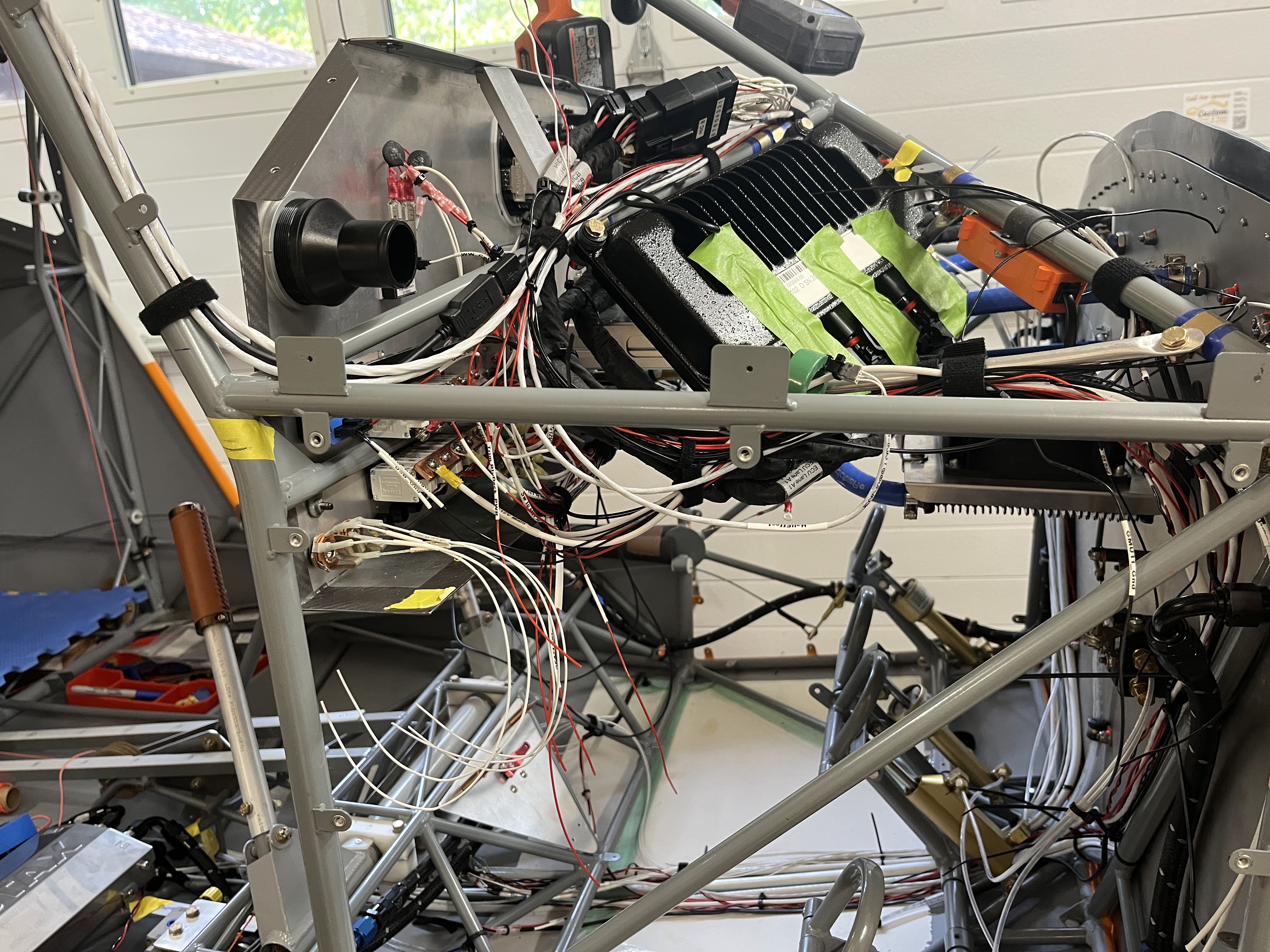
Additional work is being done to organize, bundle, and clean-up the wiring.  Still quite a bit of work to go here, but we are making progress.

Wire bundling underway, back of fuselage

Wire organization/bundling underway

Rerouting of a coolant hose was completed to provide more clearance, and Adel clamps were also installed to help hold it in place at the Rotax ring mount.  Still need to attach some fire-sleeve material at locations near the exhaust, but at least the routing is completed.

Lower coolant hose rerouted

Panel switch labels were also reprinted to reflect the current switch locations and functions. Hours: 24

Panel switch labels updated

Friday, November 4, 2022

Antennas, wiring, radiator hose, misc

The Garmin GPS was installed in the back of the plane, along with the Garmin Transponder.  These are installed along the side of the fuselage, just behind the baggage compartment.
Garmin GPS mounted in bracket next to transponder

An aluminum ground plane was installed for the GPS antenna; glued to the fabric aft of the turtledeck.  We were originally going to put the GPS antenna towards the back of the turtledeck, but determined that there would not be enough separation between the COM antenna and GPS antenna if we did that. so another small aluminum ground plane was glued to the fabric further back after first attaching a fabric backer "doily" for abrasion resistance.  The GPS antenna was then installed with 4 screws that went into nut plates that were attached to the aluminum ground plane.
Small ground plane for GPS antenna

GPS antenna installed on top of fuselage

We are in the process of modifying the routing of the coolant hoses that run from the pump to the radiator.  This radiator hose was routed between the Rotax ring mount and the Just aircraft engine mount, without a lot of clearance.  We were concerned that movement of the engine on the vibration isolation pads (shock mounts) could cause wearing on the side of the hose.  For this reason, we will be shifting it up to give more clearance.  Not a trivial task because we have to remove and remount an aluminum elbow that is screwed into the water pump to change the angle of exit first.  
Original radiator hose routing

All the avionics are now wired up, so we started to do a little cleanup of the wiring, too.  Some wires were bundled with spiral-wrap covering which does a nice job of bundling them together.  We have a lot more bundling to do, but at least we started this part of the job.  Hours: 25

Some wires with protective spiral wrap covering

Friday, October 28, 2022

Wiring Debug

We completed some final wiring to a few of the Garmin components and now have most of the wiring complete.  We are going through some checks, debug, and system configuration to make sure everything works before doing any final bundling of the wires.  

We ran into a few issues, but no major roadblocks thus far.  Initially, the Garmin G3x system did not see the transponder, but we found that the wiring of two serial ports simply needed to be swapped which fixed the issue.  We also ran into a problem where our engine monitor was not seeing both lanes of traffic from our engine computer (It only reported data from lane B, and nothing from Lane A).  We found that two of  the CANBus lines in one of the Rotax HIC connector needed to be swapped.  This was a little trickier to find, but once we swapped the lines, our engine monitor started seeing data from both lanes of our computer.  Also, one of the Lane LED warning lights was not working, but this was a minor wiring fix.  We have some additional checks to go through, but we are feeling pretty good now that all the major flight instruments are powering up and seem to be functioning.    Hours: 22

Thursday, October 13, 2022

More wiring

We continue to work on the wiring.  Most switches are wired up. Michael is currently focused on the Garmin CANBUS wiring to multiple devices, including the Garmin G3x Touch, GEA24 Engine Mgmt System, G5 Display, and GTR200B COM radio.  I've been working on the trim, Garmin GMC305 autopilot, and pitch/roll servo wiring.  We are making good progress, although it's difficult to show with pictures.  Wiring work will look messy until we are closer to completion and can bundle the wiring appropriately.  Hours: 22

Wiring work continues

Thursday, September 29, 2022

Wiring Continues

Wiring of the aircraft continues.  It looks rough now, but will be cleaned up once all the wiring is complete.  Wiring of the Garmin ADHRS (GSU25), Garmin Engine Box (GEA24), Garmin GPS Antenna GPS35A, Garmin  OAT (GTP59) and ELT were all worked on.

Garmin GSU25 getting OAT Sensor connected.

Garmin GEA24 Getting Current and Fuel Pressor sensor connected

Drill template for the GPS antenna Backer plate.

40Amp Fuse install at battery for main panel power

ELT Buzzer box with custom 3d Printed Mounting Bracket

Hours: 20

Thursday, September 15, 2022

Wiring and Misc

We had sent our fuel pumps to Lockwood Aviation Services due to a Rotax Service Bulletin.  The pumps were turned serviced and sent back to use rather quickly.  Once received the pumps were remounted in their stainless steel case.  The mount to the fuselage was reworked to make it easier to service the fuel pumps in the future.  It is also a much cleaner installation. 

Fuel Pumps received from Lockwood

We decided to install two pass-throughs in our gear tunnel for electrical cables to run from the rear of the fuselage into the cabin area.  Two plastic reinforcement rings were made and glued to the front and rear tunnel walls.  A piece of SuperFlite fabric was glued on top of the reinforcement rings and allowed to dry.  The area was repainted with gray primer.  The four holes were cut out and grommets were installed.  The grommets are there to keep cold outside air from entering in the cabin.  Finally two plastic tubes were installed, thus allowing wires to pass through.

SuperFlite Fabric over Reinforcement Plate

Grommets install (Baggage side)

Grommet and Plastic Tube installed (Cabin side)


We purchased an EarthX ETX-900VNT (vented) battery along with a matching battery box/holder.  The battery box was mounted to the battery tray provided by Just Aircraft with 8 flush mounted solid rivets in the base of the battery box.  The battery contactor was installed on the battery tray just forward of the battery box using AN4 bolts. An 4 AWG was run from the battery to the contactor as well as from the contactor to the starter solenoid running through the recently installed pass-throughs.
Battery box and contactor installed

Battery installed in battery box

4 AWG wire being installed to Starter


A ground bus block was purchased from SteinAir and mounted to the firewall in the cabin.  On the engine side, the engine block and airframe ground on the Rotax Fusebox were grounded to the ground bus block via the passthrough bolt.  The engine block was grounded since it is the return path for the starter.  A 4AWG wire was routed from the ground bus block though the cabin pass-throughs to the battery in the aft fuselage.
SteinAir ground bus block

Engine block and Fuseblock grounded

The Garmin GSB15 USB charger was wired with power and ground.  A third wire was run to turn off the internal LED by grounding it.  Looks like our GSB15 unit is defective as the LED's would not illuminate with the cable open or grounded.  Not as issue since we wanted the LED's off anyway.

Garmin GSB15 (blue unit) wired

The power and ground for the Cabin Heat fans was wired.  In the L (low) setting only the left side fan is powered.  In the H (high) setting, both the left and right fans are powered.

Cabin Heat Fan Switch

Cabin Heat Fan Installation

Wiring for the switches to control the Rotax engine was started.  Switches wired included Rotax Lane A, Lane B, Fuel Pump 1, Fuel Pump 2, Engine Start Power, EMS Backup, and Engine Start Button.

Rotax control switches being wired

Hours: 25