| Fuel outlet in firewall (engine side) |
| Fuel fitting on back side of firewall |
| Fuel outlet in firewall (engine side) |
| Fuel fitting on back side of firewall |
Continued working on the lower cowl modifications. Additional Micro/Epoxy mixture was added to fill in the fiberglass weave and imperfections. After allowing it to dry, it was sanded down. The excess fiberglass on the inside of the cowl was removed as it was no longer needed. A coating of filler/sanding primer was sprayed on the part. This is VERY revealing and immediately highlights the imperfections.
![]() |
| Lower cowl lookng nice |
![]() |
| Excess Fiberglass removed on interior |
![]() |
| Filler/Sanding Primer Sprayed |
More work was done on the lower cowl in preparation to fiberglassing in the the front openings. The 2 part foam was shaped with a 1/4" radius front edge. After removing the gelcoat, it was found that some large air pockets were in the original fiberglass layup so that needed to be repaired with filler.
![]() |
| Lower Cowl Ready for Fiberglass |
![]() |
| Fiberglass added |
![]() |
| Peal ply Removed |
With the openings for the Oil Cooler and Radiator set we set out to make the openings a little more pleasing to the eye and a little more aerodynamic. A mixture of epoxy, flock, and microbeads was added around the two openings and allowed to cure. Using a 1/4" round over bit and a router the edges of the openings were eased over, giving a nice pleasing look.
![]() |
| Oil Cooler and Radiator Openings with round over |
![]() |
| Angled view of the addition |
We also determined that we wanted to close up the cowl openings on either side of the propeller. After much discussion we decided that just closing off the bottom cowl opening (ala Steve Henry and others) would be the easiest and quickest way to achieve this. We bought some 2 part expanding foam and after taping off the area we wanted to fill the foam was mixed and poured into the area. Now we've got to shape the foam so we can add some fiberglass fabric to finish the opening close-out.
![]() |
| Expanding foam added to cowl openings |
After a lot of tweaking on the placement of the Oil Cooler and Coolant Radiator, we think we've finally nailed it down. New brackets were constructed to mount to them to the engine. Also, a single bracket ties them together. Rubber shock mounts were added for vibration isolation.
| Original bracket used to determine correct spacing |
| Final brackets installed |
With the locations fixed. The two cowl openings were planned. We drew on the cowling the maximum size and placement of the openings. We started with a 4" hole and slowly opened up the hole until we were happy with the size to hopefully provide ultimate cooling air into the two cooling devices. Our plan is to glass in some curve edges to make the openings more aerodynamic and provide some strength to the cowl in the areas that material was removed.
Hours: 24
![]() |
| Cowl Openings |
![]() |
| Another View of the Cowl Openings |
To aid in the cowl placement, we created a thin 1/4 inch circular wood spacer that is the same diameter as the spinner, and attached it to the prop flange. This is used to set the spacing between the back of the spinner and the cowl.
| wood spacer attached to back of prop flange |
We then trimmed the back edge of the top cowl in order to get it to fit into place behind the prop flange, and then attempted to attach the bottom cowl to the top. Found out we had another interference issue as the top and bottom halves couldn't quite meet up. This was frustrating as we had followed the instructions and had performed the initial cut to a "trim line" that was provided. That's what we get for following instructions.
Luckily, we still had plenty of overlap between the top and bottom, so we just needed to fill in a few holes, and adjust the bottom edge to line up with the top cowl. We used epoxy mixed with flock for added strength, and later added a few layers of dry micro (epoxy with added glass micro-balloons) to smooth it out. Some sanding was done between each step.
| bottom cowl modified to line up with top cowl |
| Planning out position of oil cooler and radiator |
After many hours of laying out our panel in software, we got a builder friend who's also building a Highlander, to cutout a temporary panel in press-board on his Shopbot CNC. A few issues were found in the cutout that will be fixed in the next pass. With some minor tweaking the panel was assembled and placed into the cockpit area to check for interference issues. None were found.
![]() |
| Panel minus Garmin G5 |
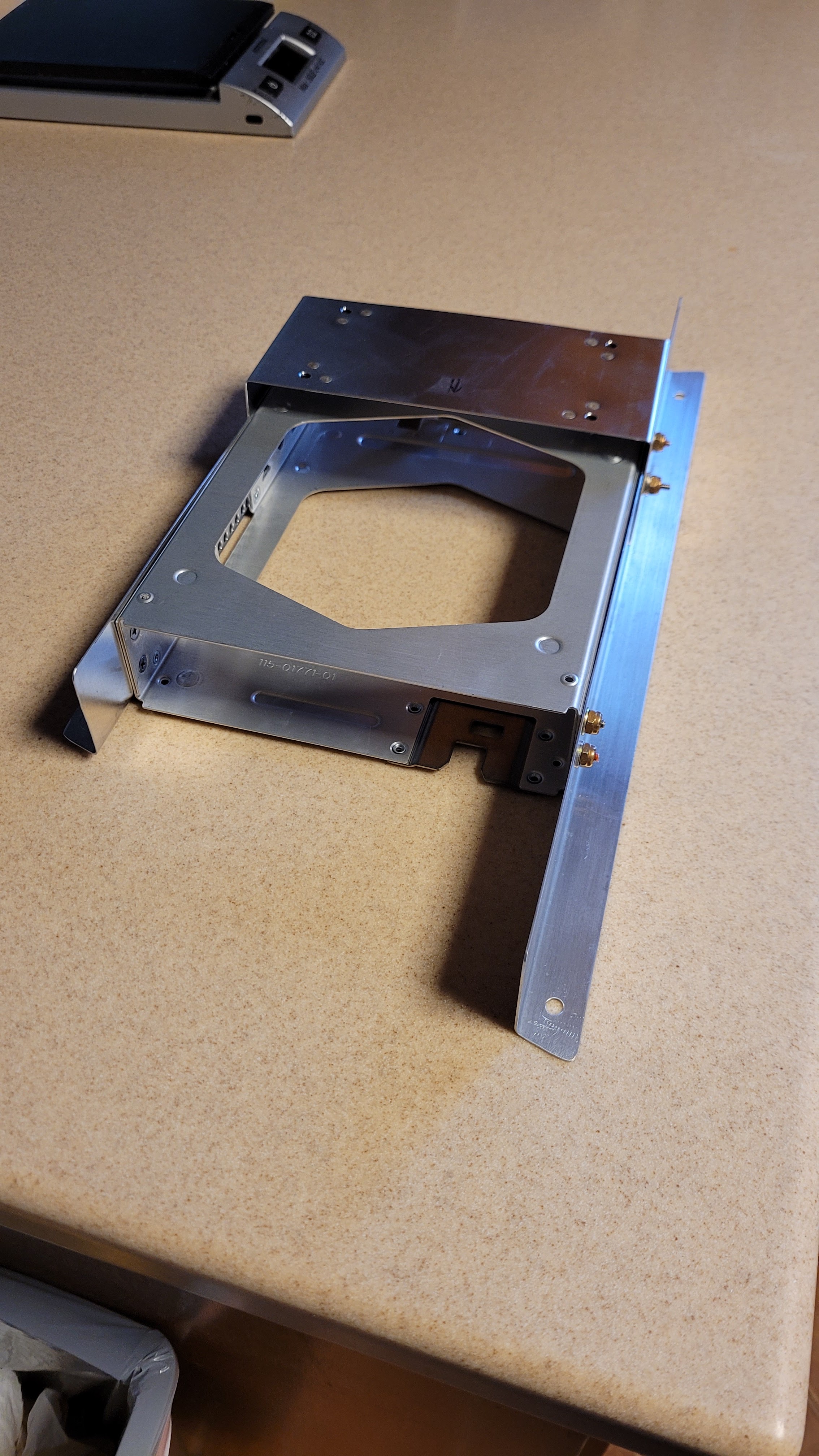
The transponder we chose for our project is the remote mounted Garmin GTX-45R. The mounting tray for the transponder needed to be mounted in the fuselage and we chose to mount it behind the baggage area. A WAAS GPS will also be needed to feed the transponder and a mount was also fashioned and attached to the transponder mounting bracket.
![]() |
| Mounting bracket installed in the aft Fuselage area |
We spent several hours making small incremental cuts on the top and bottom cowl, along with judicious sanding, in order to get the top and bottom pieces to fit together properly. At first we didn't think they could ever fit, but the fit wasn't bad once modified.
| Top and bottom cowl fit after trimming |
| Fuel site tube |
| fuel drain line with filter |
| Curtis drain valve installed on bottom |
The boot cowl was fitted in place, then match drilled to the holes in the fuselage. The lower edge was trimmed a little more. With the boot cowl in place, we could then proceed with the firewall fitting.
The engine and engine mount were removed so that we could create a posterboard template for the titanium firewall. After making the template, we laid it over the titanium firewall sheet, and trimmed it (with snips) to match.
| Template in place over firewall material |
The firewall edge was deburred, and installed with clecos. We left about a 1/4 inch gap between the top of the firewall and the boot cowling, and a gasket (provided by Just) will be installed on the firewall later which will fill this gap.
| Firewall fits nicely. |
| Firewall and engine attached |
After a lot of work on both the panel and wiring diagrams we think we've got our final layout. FreeCAD was used to layout the panel in 3D. This allowed us to check for behind the panel obstructions. The COM radio (Garmin GTX200B) was the main item we had to worry due to some cross support tubes. KiCAD was used to draw the wiring diagram (schematic). This allowed us to know how many switches and circuit breakers to place on the panel. Hours:20
| "Final" Layout |
FreeCAD: https://www.freecadweb.org/
KiCAD: https://www.kicad.org/
We hung the engine on the fuselage which was a nice accomplishment, even though this is only temporary until we can get a template for the firewall made. Once we have a template, then we will remove the engine and work on the firewall installation.
| Installing the engine |
In order to make a firewall template, we first need to fit the boot cowl, which is turning out to be a bit of an effort as we want to make sure everything lines up and that the positioning works with our aftermarket Dentz windscreen.
| Fitting the boot cowl |
We also set the windscreen in place temporarily to see how it lines up with the boot cowl. We'll have to do some more trimming along some edges of the boot cowl, but overall it looks decent.
| Fitting the boot cowl |
| Hanging the exhaust system |
| Ring mount (white) installed |
| Waterpump housing with 2 new elbows installed |
| Ed installing the waterpump |
| Michael installing coolant hoses |
We temporarily installed our new nose-gear engine mount see how how it fits, and while it was tight, it did fit. We had to add a few washers behind the lower mount point, but this was not unexpected. We checked the nosegear and it fit nicely. The firewall was removed for now as we are planning on making a template to help trim the top of the firewall once we can determine how it meets up with the cowling.
| Temporary fitting of engine mount & nosewheel |
Since we had the engine mount attached, we decided to see how the Rotax ring mount mates to it. Unfortunately, we ran into a problem. The shock-mount isolators (Large rubber isolators) that we purchased from Rotax didn't fit. We contacted the factory and found that these parts were unique and we neeeded to purchase them from the factory instead of Rotax. So we returned the Rotax parts, and are now waiting for the new parts to arrive from Just Aircraft. So we are in a bit of a holding pattern for now until the new parts arrive.
One other thing we did was remove the pitch servo and change out 4 bolts that attached it to a mounting bracket (these were a little too long). The new bolts were torqued, and the assembly was remounted in the back of the plane.
| Pitch servo with new bolts |
In the meantime, Michael has been spending many hours (days) putting together the schematics for the wiring using KiCad. A lot of time has been spent digging through all the manuals to make sure we get the wiring correct, and much time was spent sourcing parts like switches, circuit breakers, etc. Hours: 20
Several flexible fuel hoses were fabricated on the supply side, including all the hoses between the header tank and the fuel pumps. We used Jegs Pro-Flo Extreme hose which is a step up from standard synthetic rubber. The hoses have good compatibility with fuels that contain ethanol (even supporting E85 fuel). Not quite as nice as PTFE fuel hoses, but not as expensive, either. Each hose is unique as the length of hose and type of hose-ends were specifically chosen for each hose.
| Attaching a hose end |
| Fuel hoses to the gascolator and fuel pumps |
| Fuel hoses to cut-off switch |
| Return fuel line |
| Return fuel line runs |
Finally got the parts in to finish installing the brakes. We needed a 90 degree fitting on the landing gear and a straight fitting on the brake caliper. The 10" hose fit perfectly and made for a nice clean installation.
| Brake Line Installed |