Showing posts with label Firewall Forward. Show all posts

Saturday, March 4, 2023

Leak fixes, Cowl, Door frames, Control sticks

 After last engine runup, we had found we had 2 leaks, one from the brakes and one from fuel.  The brake leak was at the bottom of the Grove landing gear at a right angle fitting. The brakes were drained, and the wheel was removed to get access to the fitting.  The right angle fitting was then removed and cleaned.  Locktite thread sealer was applied, and the fitting was installed with an extra turn to ensure it fit snugly. 

Brake fitting tightened

The fuel leak was coming from a fitting that went from a T-fitting near the fuel filter to our fuel-pressure-sender.  This one was a bit complex because of all the interconnected fittings and hoses.  But this gave us a good opportunity to change our fuel-bypass orifice as we learned ours was slightly oversized ( The ideal orifice size was 0.35 mm, and ours was about 0.88 mm).  Our orifice fitting came from JEGS, and is essentially a hole drilled in a set screw, which is then screwed into a special AN fitting.  Using a small mill with a tiny drill bit, a 0.35mm hole was drilled in the center of a new stainless set screw.  This took several attempts as the tiny drill bits were easy to break, but we got it done.  The new orifice was installed, and the leaks were addressed.  After the fixes, we ran the fuel pumps (which boosts the system to 50 PSI) and checked for leaks again.  None were detected. 

Fuel leak fixed at this T-fitting

The new 0.35mm fuel-bypass orifice is in the top of this T-fitting

The cowl pieces, which had been previously primed, were sanded down with 320 grit sandpaper so that they will be ready for painting, although we won't get to that until the paint booth is back in working order.

Next we turned our attention to the doors.  We previously made a couple of center aluminum strips that cover the seam where twoLexan panels meet.  We wanted to close up the ends of these, so we filled them in with a little bit of epoxy (JB-Weld) which was sanded flat once dry.  This is mainly cosmetic, but does make it look a little nicer when installed. These strips were also sanded lightly to get them ready for priming.

Epoxy added at the ends of center door frame strips

We also wanted to decide on the color to paint the door frames.  We were originally thinking of using gray as that matched most of the interior and existing powder coat, but also considered black as that helps create more of an unobstructed view out of the airplane.  We wrapped the frame in some spare black vinyl we had to get an idea of how it would look.  We liked the result, so we will likely paint the door frames black now. 

Experimenting with black door frames

Lastly, we drilled a couple of small holes in our control sticks for the wires that will go to the push-to-talk switches.  We are going to making the control sticks removable, so plan to add a small connector that will make the wires easy to disconnect.   Hours: 27

Hole drilled in control stick

Thursday, February 23, 2023

Engine test #2, more Cowl work, and misc

We had a run of nice weather, so decided to prep the plane for another ground run.  We bolted the propeller back on, carefully setting the pitch of each blade to keep them within 0.3 degrees of each other.  We decided to keep the cowling on for this test since we had just finished installing the Skybolt fasteners in them.

This time we ran the engine for a longer test period (about 15 minutes), and also ran up briefly at full power to verify the prop pitch.  At full power, our engine RPM needed to fall between 5100 and 5800 RPM to ensure the blade pitch is within limits and safe to fly (per guidance from our prop manufacturer, E-Props).  Ours came up to 5200, so it is good.  We may need to change the prop pitch a bit later once we get to the flight testing stage.  E-Props recommends pitching for 5500 RPM when in flight at full power.

Michael behind the controls for the 2nd engine test run

The test run went well, although we did uncover a few issues after looking everything over after the test run.  We found some drips down by the right brakes, and found two brake fittings that had drips and need to be addressed.  We also found a bit of fuel leaking around the fuel pressure sensor that we will fix.  This shows how important these early tests are as they help flush out these type of issues.  Some brake line compression fittings and a few new fuel hose fittings were ordered and will be installed once they arrive. 

We also did some additional work on the cowling to improve the surface finish.  This included adding a little more filler and sanding. The front ledge of the boot cowling was also trimmed back a bit (about an inch). We decided to shoot a light coat of primer on the three cowling pieces, as this can help to find remaining defects in fiberglass.  We did this outside since our paint booth is currently full of tools and parts.  Not sure why this works so well, but just this little coat of primer really did help highlight some of the remaining irregularities in the surface that we will now fix.  

Light coat of primer on the three cowling pieces

We also wanted to address the cockpit down tubes that are directly in front of the pilot and passenger.  We decided to wrap them with a matte black vinyl to hopefully help mitigate reflections on the windscreen. A 2" wide strip of vinyl perfectly went around the circumference of the two tubes. Hours: 21

Black matte vinyl added to down tubes
 

Thursday, January 12, 2023

Misc (Brakes, Cowl, Header Tank)

We've been working on a lot of various parts over the last few days.  We finally got all the brake plumbing complete and got the brake fluid bled. It took some effort to remove all the air bubbles.

The front of the cowl received 3 layers of fiberglass over the foam shape in near the propeller.  After allowing the epoxy to cure a lot of sanding was done to smooth the transition.  We're planning on adding fasteners on the inside of the cowl air openings hear the propeller hub.  This area needed some attention with fiberglass to give enough room for fasteners.

To make the site tube more visible on the header tank, Ed is fabricating an aluminum shroud that will also have a hash pattern that will greatly improve the header tank level.  This is just a back-up since we also have a fuel level sensor on tank that turns on a red LED on the dash if the level ever drops below a set value.

Hours: 8

Peel-ply over the top of the fiberglass addition on the upper cowl

Fixing the lower cowl to allow for fasteners

West System epoxy in use

Ed working on header tank site gauge shroud

Wednesday, January 4, 2023

Brakes and Cowl 2

Ed continued working on the brakes.  The two master cylinders were removed and rebuild kits from Matco Mfg were installed.  Ed had to fabricate an assembly jig to help with the installation.

Ed installing one of the rebuilt master cylinders

Michael worked on the cowling modifications.  After allowing the glue to setup overnight, the cowl was split and reinstalled on the airframe.  With the aid of a homemade jig and some spacers the foam was sanded down to give the spacing needed making sure the face was parallel to the propeller hub.  Once the spacing was correct.  The shape was filed and sanded.

Foam sanded into shape

Testing with propeller spinner

Hours: 4

Monday, January 2, 2023

Brakes and Cowl

Finally getting back in the swing of things after taking a break over Christmas. 

Brakes: After some more adjustments, we no longer have brake fluid leaking from any of the fittings, but are having issues bleeding the brakes.  The right brake has air infiltrating into the lines somewhere around the passenger-side cylinder. Also, the left brake was bled but over time has gradually been getting some air bubbles in the lines near the left master cylinder.  After attempting several times to bleed them without success, we suspect some of the internal brake cylinder seals are leaking, and perhaps sitting on the shelf for 8+ years before installation didn't help.  We bought Matco brake rebuild kits and plan to replace all the seals on the brakes before bleeding the brakes again.  

Draining brake lines in prep for additional work

Cowl: With the prop installed on the airplane, we are not happy with the aesthetics of how the front of the cowl lines up with the spinner.  Because of this, we're going to do some fiberglass cowl modifications to make this look better.  It may reduce drag a bit too, but probably not much.

Gap between spinner and cowl on pilot side

We are gluing some styrofoam to the front of the cowl which we will later shape and use as a form for laying up the fiberglass.  Hours: 10

Foam glued to front of cowl

Wednesday, December 14, 2022

Propeller on, oil filled, fuel and coolant systems work

We installed our new prop, which is a three bladed carbon-fiber propeller with a diameter of 190cm, made by a French company called E-Props.  Hopefully it performs as good as it looks.

Prop installed on engine.

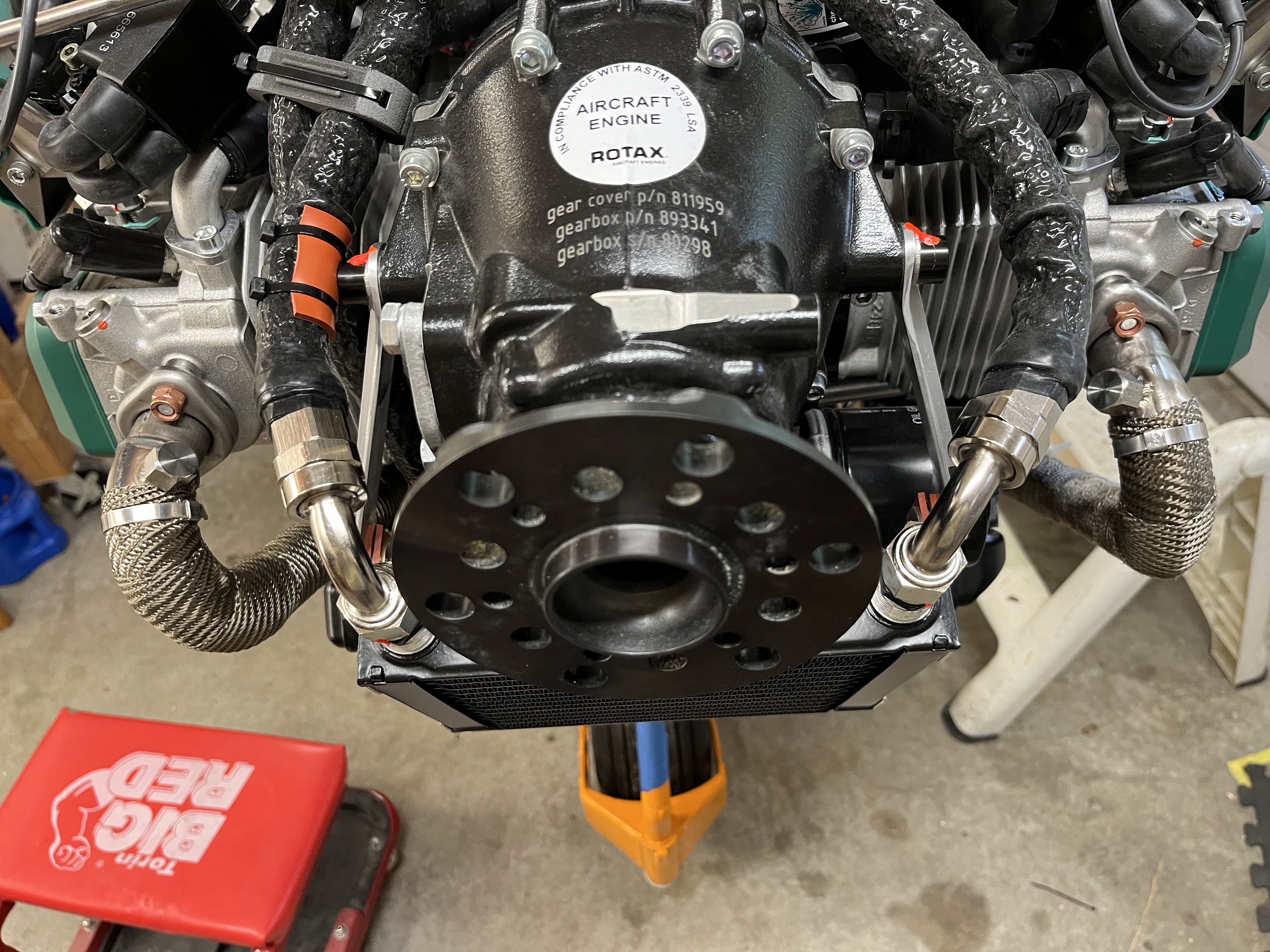
After double checking all the oil connections, we added oil to the engine (it's a dry sump system), and purged the air from the system by following Rotax's procedure.

We've been chasing some leaks in both the fuel and coolant systems.  Original debug was done by pressurizing the system and spraying the connections with soapy water, but this just wasn't good enough as we couldn't identify any of the leaks.  We then bought a stethoscope (with an air leak adapter), an ultrasonic leak tester, and some super-bubbly fluid from Rectorseal (all fairly cheap from Amazon).  All three were used and help find the leaks in the fuel system which were from connections directly beneath the header tank.  One of the fittings under the header tank needed to tightened (a standard pipe thread fitting), and two hose clamps needed to be tightened.  We still had an issue with one of the hoses beneath the header tank, so I replaced a 6" hose section and reclamped. This time it worked and the fuel system now holds pressure without leaks. 

These hose connections were leaking

We also identified a leak on the coolant system, and tracked it down to a bypass valve on the cabin heater line.  The valve itself felt a bit loose and likely defective, so a new valve was ordered and installed.  This new valve has a better, smooth feel to it, so we feel better about its quality.  Other coolant hose clamps were also tightened a bit to help ensure the system was sealed.  Hours: 17

Replacement Bypass valve installed

Thursday, August 11, 2022

Panel Modification and Misc

 We ordered copper buss bar material from Aircraft Spruce.  We drilled the holes based on the spacing of the Klixon Circuit Breakers (CB).  We quickly found that the vertical spacing between the two rows of CB's would not work.  The bottom row of CB's were too close the the bottom panel edge and too close the the upper row of CB's causing shorting issues.  There wasn't much space to move things around without a major change.  After some back and forth on the best solution we came up with the new location as shown in the picture.

New CB location

You can see the five plugs installed in the old location.  The ELT had to be moved up by 1/2".  The locate the new holes on both the CB's and ELT, Michael printed some drill guides on his 3D printer.  This worked wonderfully.

Top: ELT Drill Guide
Bottom: CB Drill Guide

With the new location, we now have room to start wiring to the CB's.  Due to the thickness of the Buss Bar material from Aircraft Spruce, new 6-32 screws were ordered.

CB's and Buss Bar trial fit

We were using two worm gear clamps to temporarily attach the oil tank in the engine bay.  We finally ordered the correct parts, installed them and safety wired them.

Oil tank straps installed

The position and installation details for the  parking brake valve was finalized. A spacer had to be installed on the firewall to make the Bowden cable function more precisely.

Parking Brake Valve Installation

Hours: 16

Wednesday, August 10, 2022

Fuel and Oil hoses, Fusebox, Misc

The hoses to the differential pressure sensor were were connected and torqued.  There is a 4An line running to a T-fitting near the fuel filter, and a 3AN line runs from the back of the sensor to the airbox.

Differential Pressure Sensor on firewall

All fuel fittings from the firewall pass-thru to the engine were torqued and marked with torque seal.

Fuel and fuel filter lines torqued

The fuse box, which is attached to the firewall, was rotated 180 degrees so that the connectors are now pointed down.  The manual does not specifically call out an orientation, but this is the placement that most builders are using.  This orientation should help prevent any moisture from seeping into the enclosure through the connector openings.

Many other hoses forward the firewall were tightened and torqued to the appropriate value, then marked with orange torque seal. This included all other fuel lines, oil lines, and an air line running from the differential pressure sensor to the airbox.  A few silicone  isolation pads were attached at points where there was any possibility of rubbing. Also a few wire-ties were added to keep hoses and cables in place. 

3AN line to airbox torqued

Oil lines torqued to the oil cooler. Red protective pad attached to oil line.  

Oil lines running to thermostat torqued and marked

Since our firewall is titanium, the general recommendation is to use stainless steel fasteners instead of cadmium-plated steel in order to prevent potential galvanic corrosion.  Because of this, we replaced several of the fasteners on the firewall with stainless steel parts.  The most difficult replacement was a couple of larger spacer washers at the bottom of the firewall which were very tight, but we got 'er done.
Hours: 17
Several firewall fasteners replaced with stainless steel parts

Washers between firewall and frame replaced

Tuesday, June 28, 2022

Coolant Extension, Oil Lines and 3D Printing

Now that we have "most" of the windscreen and skylight work out of the way, we moved back to more firewall forward work.  We've been fighting with the water pump elbow on the Rotax 912iS engine.  No matter where it is placed, the engine Ring Mount interfered.  Luckily Edge Performance in Norway has come up with a solution that works well.  They provide an extension section that moves the elbow out away from the engine allowing you to route your coolant hose around the Ring Mount. 

Extension as delivered, Included o-ring and new bolts

Extension installed

We also decided to make new oil and fuel hoses.  We had originally planned to use some high-performance light weight racing hose, but after many attempts doing pressure testing on the hose assemblies, we could never eliminate a very slow leak.  We switched gears and are using a more standard hose.  Luckily, since the previous hoses were already made we just had to duplicate the lengths for the new hose assemblies. Took us a whole day to make the new hoses, but much more pleased with the outcome!

To try and clean up the firewall forward, Mike designed some hose organizers and 3D printed them.  They came out well and help organize and route the hose lines over the engine.

3D Printed Hose Organizers

We also wheeled the airplane outside for a few "glamour" shots in the sunshine.  We've made a lot of progress since the last time it was outside.

Hours: 15

Proud Builders

Straight on View

Cockpit/Panel View

Side View


Wednesday, June 8, 2022

Panel, Fusebox and ECU installed

 The Rotax Fusebox was placed on the engine side of the firewall per Rotax recommendations.  We spent some time looking for a good mounting locations and the location in the attached picture is the best we could come up with.  Not super convenient, but acceptable.

Rotax Fusebox Mounting Location

A lot of work has been put into getting the panel installed into the airplane cockpit.  As mentioned earlier, we had a local builder cut out our panel on a Shopbot CNC machine.  A little cleanup was needed on the panel.  We also had to cut one hole by hand for the Rotax Debug port as we forgot to add that in the computer software.  Once the panel as cleaned up, we used  our large brake to bend the four flanges that help stiffen the panel and provide some safety shielding at the bottom.  Since we have a lower end brake, we had to use some sacrificial material to make sure we got the bend radius we needed for the 0.040" aluminum we used on the panel.

After the panel was bent, a gray carbon fiber vinyl wrap was applied to the panel.  The vinyl was removed from the holes in the panel using a sharp razor blade and a good X-acto  knife.

On the lower portion of the panel, there are three points that attach the panel to the fuselage.  Two screws hold the panel on the outer portions and the throttle control secures the panel in the center.  The top of the panel needed to have some supports .  Two supports were fashioned out of extruded aluminum angle. The one on the right side needed to have some features added to clear the Garmin G3X.  Mike got he shape and bends in the aluminum set and Ed followed up by welding the complex bend to make the part stronger.  As can be seen in the attached picture, the panel supports go from the top of the panel to some fuselage support tubing behind the panel.  The radio also needed some additional support at the back, due to its long moment arm.  A support was fashion to connect it to a fuselage support tube, again shown in the attached picture.

Michael Installing Panel

Temporary Panel Labels

Panel and Radio Supports added

The Rotax ECU needs to be installed in the cockpit area.  We spent a lot of time trying to find a good location that wouldn't interfere with the side NACA ducts or the cabin heat radiator.  We finally found a location on the left side behind the panel suspended from some fuselage support tubing.

Hours: 15
Rotax ECU Mounting


Monday, May 23, 2022

Top Cowl and Firewall work

 The Silicone/Fiberglass baffle seal was received from Aircraft spruce and cut to the desired shape.  We chose 2" of overlap as our starting point but later trimmed it down to about 1", which worked much better at contouring to the boot cowl shape.  The backer bracket was used to locate the holes and the holes where punched in the silicone with a hand bunch.  Currently the baffle seal is cleco'd in place awaiting rivets.

The firewall was finally riveted to the fuselage, replacing the clecos that had been holding it in place.

Baffle Seal Cleco'd in Place

We decided we wanted an access door in the top cowl so that we could quickly check the oil level in the oil tank.   Michael had some left-over Hartwell latches from his previous project that fit the bill perfectly. We also ordered a hidden hinge from Aircraft Spruce.  The access door needed to be large enough  to reach down and remove the oil tank lid.  Once that was determined, an extra lip was needed for the door to close against.  We chose a 1/2" lip.  The access door was marked on the top cowl and cut out with a Dremel tool.  A new door was fashioned out of 0.040" aluminum and it was coaxed into shape since the top cowl is curved.  To create the needed lip for the door to seal against we needed to use fiberglass/epoxy.  The original piece of fiberglass that was cutout of the top cowl was coated with packing tape, which epoxy doesn't stick to. It was taped back into its position on the top side.  Some modeling clay was put in the cut gap to create a smooth inside surface.  Four layers of fiberglass was layed up and allowed to dry.  Once cured, the old door was removed.  The 1/2" lip was drawn and the excess fiberglass was cutout with a Dremel.  The cutout for the Hartwell latches with made on poster board and transferred to the metal access door.  The holes were cutout and each latch were installed with 4 solid rivets.  Next the hinge location was set. The holes were drill in the cowl and access door and then riveted in place  with solid rivets.

Oil Access Door with Fiberglass Lip

Oil Access Door with Latches and Hinge Installed


The throttle cable pass-thru on the firewall was installed.  We bought a "eyeball" firewall pass-thru from Aircraft Spruce that worked out nicely.  Once tightened, it provided a nice sealed port for the throttle.

Hours: 20

Cabin Side of Throttle Cable Eyeball Port

Engine Side of Throttle Cable Eyeball Port