Friday, August 26, 2022

Radiator hoses & Seatbelt anchors

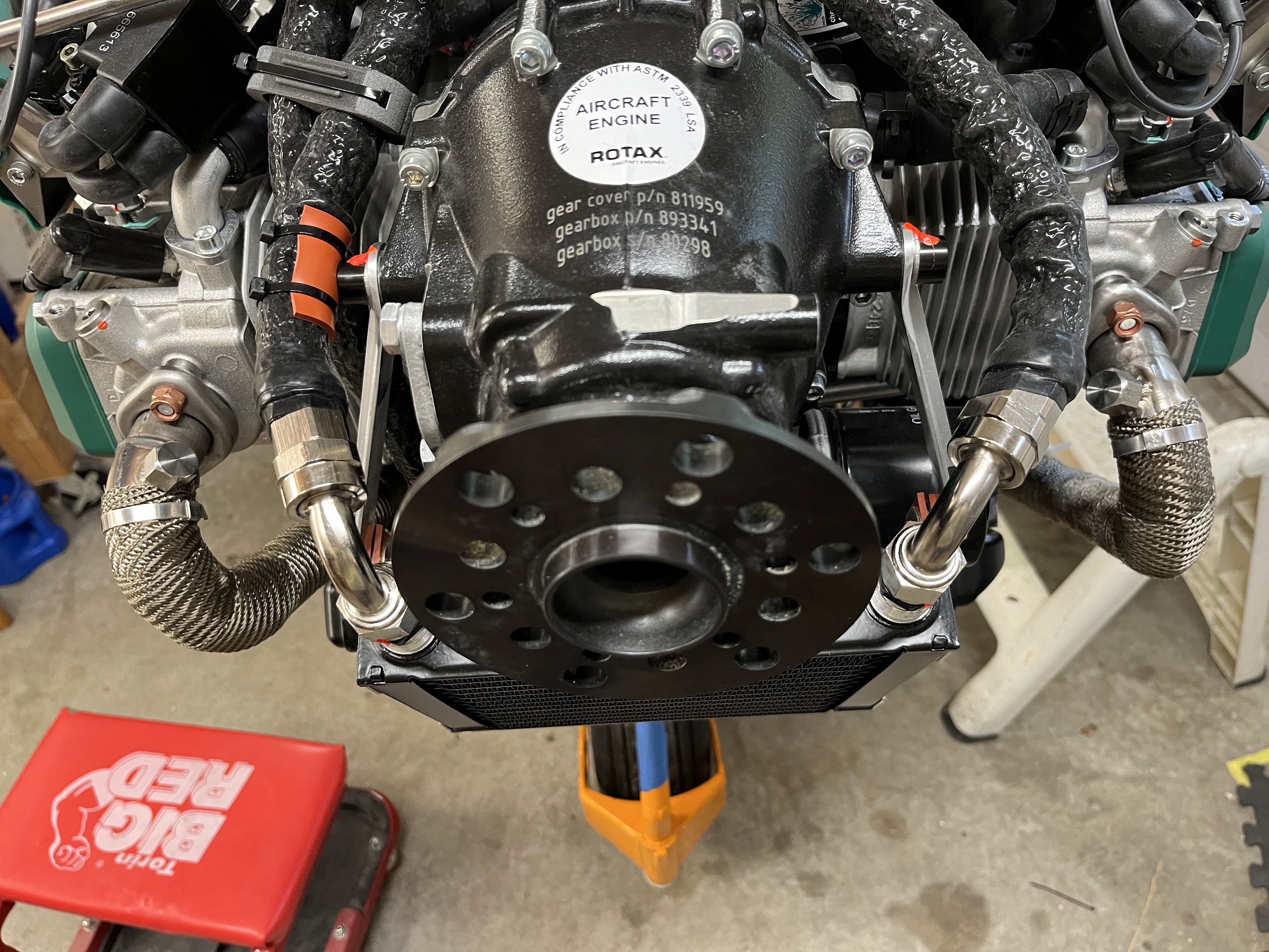
We modified the coolant connections on the right side because we didn't have enough clearance between he exhaust and the radiator hose.  We also decided to change from standard rubber hoses (which have a 5 year replacement schedule) to silicone hoses that last much longer.  The silicone hoses also have a higher temperature rating which is nice.

Radiator hose connection to water pump

Hose connections to radiator

We also made 4 cables that will be used to anchor the seatbelts.   1/8" stainless cable was slid through a 10" piece of blue polyurethane jacket (1/4" diameter).  The cable ends wrap around AN111 cable bushings, and the ends were then swaged.    Hours: 9


Sunday, August 21, 2022

Door Lexan

Work on the two door Lexan pieces started.  There have been several methods to accomplish the door Lexan installation.  After doing research and asking questions on Facebook and WingsForum, we settled on two separate pieces of Lexan and an aluminum strip to cover the seam.  The door frames were laid on the Lexan and a rough shape was drawn leaving about 2" of overhang.  The shape was cut-out.  The Lexan was first attached to the top section along the door hinge. 

Getting ready to drill top tops along Hings

Then the holes were located and drilled down the two side supports to the middle support.

Drilling down the side supports

Top section drilled and cleco'd

A line was precisely drawn down the middle of the middle support.  The Lexan was removed from the door frame and cut along the line.  Ed's hand was the most steady, so he got this job.  Once the cut was made, the edges were cleaned up with files and sandpaper.  Next, the bottom section was positioned.  Due to the curvature of the doors, the bottom Lexan had to be positioned an then excess material had to be removed to follow the upper Lexan piece over the middle door support.  Once the bottom Lexan fit properly the drilling of holes was completed.  TIP:  To locate the door supports without removing the protective material on the Lexan, a bright light was positioned below Lexan allowing the shadow of the door frame to shine through.  You can see this in the very first picture.

Next, a 1/2" x 1/2" x 48" piece of aluminum u-channel was ripped on the bandsaw to leave a 1/2" x 1/8"x 48" piece of aluminum.  The aluminum u-channel was placed on the door and the peak of the middle door support was located.  A pilot hole was drilled in the u-channel at this position.  The remaining holes in the u-channel were located and drilled.  A pilot hole was also drilled at the peak of the door middle support.  The u-channel was cleco'd to the middle door support.  Using the pilot holes in the u-channel as guides,  the remaining holes were drilled into the middle door support working from the peak to each side.  All holes were up-drilled to their final #30" size.


First Door (Left Side) complete

The complete process was repeated for the second door.

Second Door (Right Side) completed and tested

Hours: 20

Thursday, August 11, 2022

Panel Modification and Misc

 We ordered copper buss bar material from Aircraft Spruce.  We drilled the holes based on the spacing of the Klixon Circuit Breakers (CB).  We quickly found that the vertical spacing between the two rows of CB's would not work.  The bottom row of CB's were too close the the bottom panel edge and too close the the upper row of CB's causing shorting issues.  There wasn't much space to move things around without a major change.  After some back and forth on the best solution we came up with the new location as shown in the picture.

New CB location

You can see the five plugs installed in the old location.  The ELT had to be moved up by 1/2".  The locate the new holes on both the CB's and ELT, Michael printed some drill guides on his 3D printer.  This worked wonderfully.

Top: ELT Drill Guide
Bottom: CB Drill Guide

With the new location, we now have room to start wiring to the CB's.  Due to the thickness of the Buss Bar material from Aircraft Spruce, new 6-32 screws were ordered.

CB's and Buss Bar trial fit

We were using two worm gear clamps to temporarily attach the oil tank in the engine bay.  We finally ordered the correct parts, installed them and safety wired them.

Oil tank straps installed

The position and installation details for the  parking brake valve was finalized. A spacer had to be installed on the firewall to make the Bowden cable function more precisely.

Parking Brake Valve Installation

Hours: 16

Wednesday, August 10, 2022

Fuel and Oil hoses, Fusebox, Misc

The hoses to the differential pressure sensor were were connected and torqued.  There is a 4An line running to a T-fitting near the fuel filter, and a 3AN line runs from the back of the sensor to the airbox.

Differential Pressure Sensor on firewall

All fuel fittings from the firewall pass-thru to the engine were torqued and marked with torque seal.

Fuel and fuel filter lines torqued

The fuse box, which is attached to the firewall, was rotated 180 degrees so that the connectors are now pointed down.  The manual does not specifically call out an orientation, but this is the placement that most builders are using.  This orientation should help prevent any moisture from seeping into the enclosure through the connector openings.

Many other hoses forward the firewall were tightened and torqued to the appropriate value, then marked with orange torque seal. This included all other fuel lines, oil lines, and an air line running from the differential pressure sensor to the airbox.  A few silicone  isolation pads were attached at points where there was any possibility of rubbing. Also a few wire-ties were added to keep hoses and cables in place. 

3AN line to airbox torqued

Oil lines torqued to the oil cooler. Red protective pad attached to oil line.  

Oil lines running to thermostat torqued and marked

Since our firewall is titanium, the general recommendation is to use stainless steel fasteners instead of cadmium-plated steel in order to prevent potential galvanic corrosion.  Because of this, we replaced several of the fasteners on the firewall with stainless steel parts.  The most difficult replacement was a couple of larger spacer washers at the bottom of the firewall which were very tight, but we got 'er done.
Hours: 17
Several firewall fasteners replaced with stainless steel parts

Washers between firewall and frame replaced

Friday, July 22, 2022

Fuel Lines and Temperature Probe

Took care of a few misc. items.  Along the right side, we secured the fuel line with Adel clamps, and also made a small angle clamp to secure it to the back corner of the fuel pump housing.

Fuel line clamped

Small bracket and clamp at fuel pump housing

A temperature sensor was installed by adding a small spacer for a longer (34mm) M5 bolt that attaches through the fuel rail cover.  This puts the sensor near the engine air inlet as recommended.

A differential fuel pressure sensor was installed on the firewall.  A short 4AN fuel hose is attached on one side, and a 3AN hose (for air pressure) attaches to the other side.  The other end of the 3AN hose attaches to the airbox. 

We added a fitting to the airbox for the other end of the 3AN hose for the differential pressure sensor.  This included an M6 standoff with a 14mm long stud (purchased from McMaster-Carr), and then an M6 to 3AN fitting.  Some additional work was also done secure fuel and air lines forward of the firewall.  Hours: 12
3AN fitting on airbox

Monday, July 18, 2022

Glareshield and hose work

Added some fire sleeve material around several hoses near the exhaust

Firesleeve material around hoses

We created a template out of posterboard for the glareshield, with cutouts for the center windshield tubes.  The sides of our glareshield are angled which makes this piece a little more complicated than the standard one.   An aluminum glareshield was cutout using the template, and some additional trimming was done to get the basic fit.  We drilled the holes for front attachment screws, but will wait until the windshield is installed before doing any final fitting.

Glareshield template

Aluminum glareshield, top view
Glareshield

We had planned on installing the exhaust springs and bolts, but found that some of the springs don't have enough clearance.  We may be able to get enough clearance for an exhuast pipe on the front right side by bending one of the exhaust hooks slightly.  The front left exhaust pipe has a spring that presses against the protective installation one one of the radiator hoses.  We will need to either adjust the hose routing or the exhaust to ensure we have more clearance there..  Hours: 17

Tuesday, June 28, 2022

Coolant Extension, Oil Lines and 3D Printing

Now that we have "most" of the windscreen and skylight work out of the way, we moved back to more firewall forward work.  We've been fighting with the water pump elbow on the Rotax 912iS engine.  No matter where it is placed, the engine Ring Mount interfered.  Luckily Edge Performance in Norway has come up with a solution that works well.  They provide an extension section that moves the elbow out away from the engine allowing you to route your coolant hose around the Ring Mount. 

Extension as delivered, Included o-ring and new bolts

Extension installed

We also decided to make new oil and fuel hoses.  We had originally planned to use some high-performance light weight racing hose, but after many attempts doing pressure testing on the hose assemblies, we could never eliminate a very slow leak.  We switched gears and are using a more standard hose.  Luckily, since the previous hoses were already made we just had to duplicate the lengths for the new hose assemblies. Took us a whole day to make the new hoses, but much more pleased with the outcome!

To try and clean up the firewall forward, Mike designed some hose organizers and 3D printed them.  They came out well and help organize and route the hose lines over the engine.

3D Printed Hose Organizers

We also wheeled the airplane outside for a few "glamour" shots in the sunshine.  We've made a lot of progress since the last time it was outside.

Hours: 15

Proud Builders

Straight on View

Cockpit/Panel View

Side View


Wednesday, June 22, 2022

Windshield and Sunroof

Made good progress on the windshield installation.  Holes were drilled (and deburred) in the boot cowl, the windshield brackets (top and sides), the cap strip, and the acrylic windshield itself.  Special drill bits were used to drill the plastic to prevent damage to the windshield. The windshield edges were also trimmed and sanded smooth, and temporarily attached with clecos.   We're very happy with the fit. 

Ed drilling lower holes in the windshield

Michael sanding edges of windscreen

The sunroof is a separate piece of plastic which is more flexible than the windshield.  The sunroof shape was roughly cut out of a 4x8 sheet of Lexan, then clamped in place on top of the fuselage with 1/8" spacing from the windshield along the front.  Holes were drilled for screws along the front (match drilled to existing holes in the windshield bracket).  Then holes marked and drilled along the sides and back for rivets.  

Made a stupid mistake by drilling a hole in the wrong place when our hole-duplicator tool was accidentally aligned with an existing rivet instead of a hole in the bracket.  This resulted in an unwanted hole along the back edge of the sunroof.  We thought about the best way to recover, and decided to just make a new sunroof because we had extra Lexan material.  The second one came out perfect.  Clecos were installed to hold it all in place after the holes were drilled and deburred.  We marked the edges and began trimming the excess material around the perimeter of the sunroof, but still have a little work to do to get all the edges trimmed nicely.  Hours: 20

Sunroof installation in progress

Front bracket with holes drilled for sunroof and windshield

Friday, June 17, 2022

Windshield

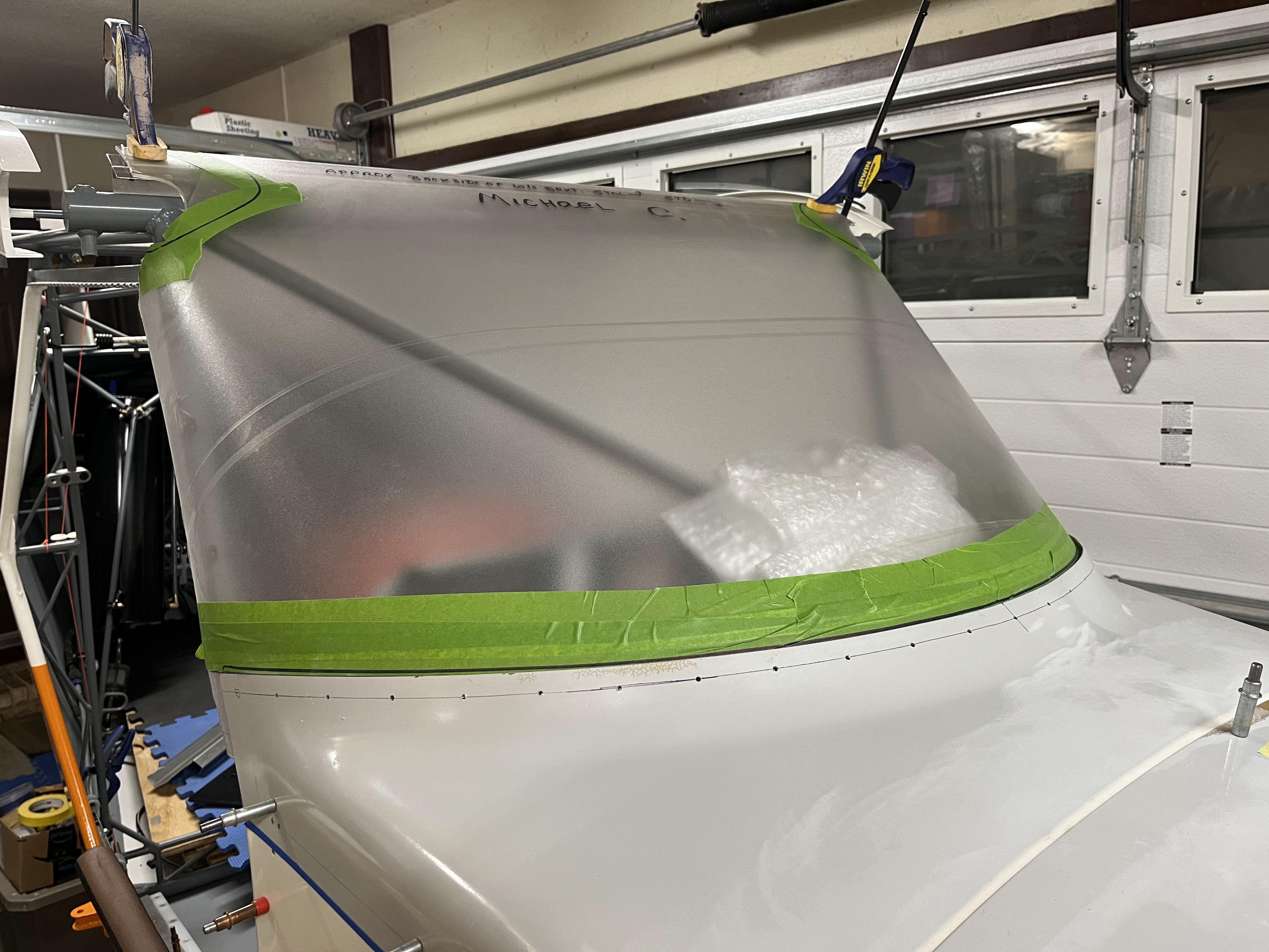
We started working on the windshield this week.  We are installing a "Steve Dentz" windshield that is pre-formed instead of the standard windshield that is bent into shape from a flat sheet.  

The top windshield bracket is made up of 2 aluminum pieces riveted together, with a cap strip that will be attached across the top.  The angle of the 2 pieces didn't quite line up with our roofline, so we bent them slightly with a 36" brake to get them to line up. The two pieces were trimmed and riveted together.  The bracket was clamped to a long straight edge to ensure it lined up with the top of the root rib, and holes were drilled through the fuselage tabs into the bracket so it could be cleco'd in place. 

Windshield bracket clamped in place

Holes were drilled approximately every 4 inches along the top and back edge of the cap strip, and match drilled holes in the windshield bracket (these are the locations where the windshield and sunroof will be screwed into place), and then additional holes were drilled for the rivets for attaching 6-32 anchor nuts.  The anchor nuts were then riveted in place to the windshield bracket.

Drilling for an anchor nut

The windshield bracket was cleco'd in place, and the windshield was set in place.  The three pieces of the cowling were also attached to check the fit of the windshield.  The windshield was trimmed slightly to ensure there was no interference.  Locations for screws along the boot cowl were marked every 2 inches, and then 1/8 inch pilot holes were drilled in the boot cowl.  Still have a ways to go to get the windshield installed, but making good progress.  Hours: 12

Windshield fitted and pilot holes drilled in boot cowl

Monday, June 13, 2022

NACA air duct work

Made some fancy holes in the two aluminum side panels to match the profile of our small plastic NACA air ducts.

Hole cut for NACA duct

The two NACA ducts themselves were primed and painted white.

Ducts painted white

Had issues with the paint on one of the side panels.  After cutting the hole, the paint lifted and had a nice tear.  Looks like the primer didn't hold well in this area, so I had some fix work to do.  

Paint peeled up

The area was sanded and re-primed it with a different brand of metal primer (Polyfiber).  Tried to touch up the white paint with an airbrush, but it didn't come out very smooth, so I'll just sand and repaint it later when we paint some of the other unfinished parts, such as the cowl or turtledeck.   Hours: 15

Wednesday, June 8, 2022

Panel, Fusebox and ECU installed

 The Rotax Fusebox was placed on the engine side of the firewall per Rotax recommendations.  We spent some time looking for a good mounting locations and the location in the attached picture is the best we could come up with.  Not super convenient, but acceptable.

Rotax Fusebox Mounting Location

A lot of work has been put into getting the panel installed into the airplane cockpit.  As mentioned earlier, we had a local builder cut out our panel on a Shopbot CNC machine.  A little cleanup was needed on the panel.  We also had to cut one hole by hand for the Rotax Debug port as we forgot to add that in the computer software.  Once the panel as cleaned up, we used  our large brake to bend the four flanges that help stiffen the panel and provide some safety shielding at the bottom.  Since we have a lower end brake, we had to use some sacrificial material to make sure we got the bend radius we needed for the 0.040" aluminum we used on the panel.

After the panel was bent, a gray carbon fiber vinyl wrap was applied to the panel.  The vinyl was removed from the holes in the panel using a sharp razor blade and a good X-acto  knife.

On the lower portion of the panel, there are three points that attach the panel to the fuselage.  Two screws hold the panel on the outer portions and the throttle control secures the panel in the center.  The top of the panel needed to have some supports .  Two supports were fashioned out of extruded aluminum angle. The one on the right side needed to have some features added to clear the Garmin G3X.  Mike got he shape and bends in the aluminum set and Ed followed up by welding the complex bend to make the part stronger.  As can be seen in the attached picture, the panel supports go from the top of the panel to some fuselage support tubing behind the panel.  The radio also needed some additional support at the back, due to its long moment arm.  A support was fashion to connect it to a fuselage support tube, again shown in the attached picture.

Michael Installing Panel

Temporary Panel Labels

Panel and Radio Supports added

The Rotax ECU needs to be installed in the cockpit area.  We spent a lot of time trying to find a good location that wouldn't interfere with the side NACA ducts or the cabin heat radiator.  We finally found a location on the left side behind the panel suspended from some fuselage support tubing.

Hours: 15
Rotax ECU Mounting